
 LinkBack URL
 About LinkBacks


Olderdan's lathe tumbler post SB lathe reverse tumbler mod. was highlighted in the recent HMT members emailing. That reminded me to make this related post which I have been meaning to do for a while.
Sometime back I posted about some modifications that I made to the drive system and head stock of my lathe
Improving a lathe spindle head.
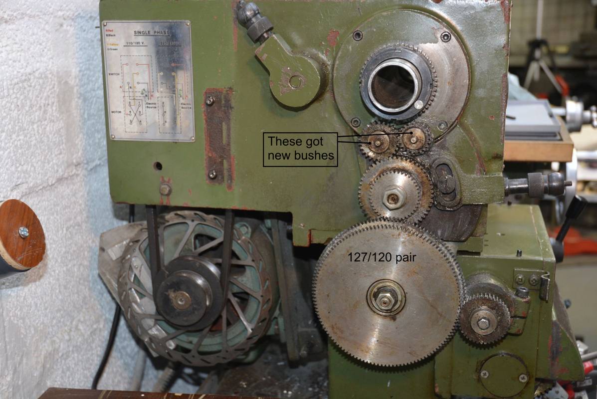
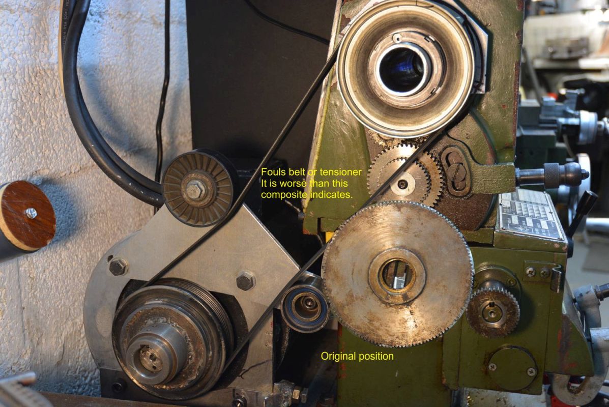
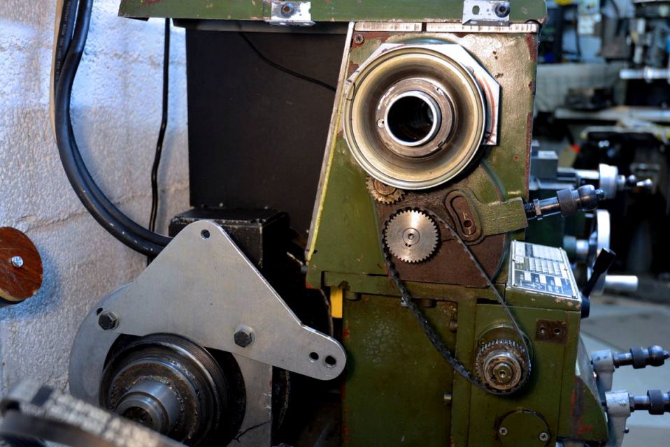
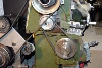
At the time of those modifications I was planning on fitting ball screws and motorising the feed shafts. So I did not bother ensuring that the original feed mechanism, specifically the change gears, remained functional. As things have turned out I just have not had time to do that and I got fed up with always hand feeding the saddle and cross slide. I decided to refit the feed gearbox which gave no problems, then the change gears but the new drive belt was in the way of the big 120/127 gear pair as shown next. To the left is the original drive system showing the change gears, the next shows the clearance problem with the new drive system in place.

Click images for full size.
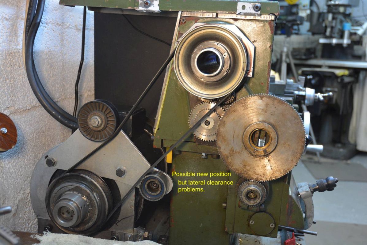
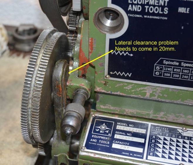
I could have fitted a longer drive belt and moved the idler pulley, but that was the drive side of the belt and I wanted to keep it as straight as possible. I only fitted the idler to prevent belt flap at specific resonant and harmonic speeds. I saw another way of fitting that gear pair by moving them to the other side of its driving pinion and the pinion on the gearbox input as shown in the first photo below but that had a lateral clearance problem shown in the second.

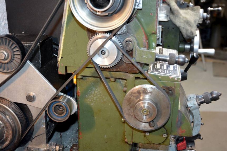
After a bit of head scrathing I decided to change tack and look at driving it with a belt. I had a toothed belt that was close enough to investigate the feasibility. As the next photo shows it looked worth considering.
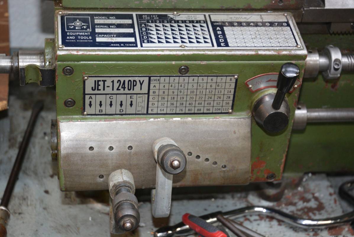
However, my leadscrew is imperial but I work in metric, so to be able to screwcut in metric I would have to retain the 127/120 multiplier of the gear pair being replaced but 127/120 cannot be divided down any more as integers. That would need two large toothed pulleys and there was no room for that. That meant if I used a belt I would have to use smaller pulleys and forget about screw cutting. Well, that is no problem. I have a CNC mill which I can use as a CNC lathe by putting the work piece in the spindle, or I could use it in thread milling mode. My son also got a new lathe recently so I could use his. So that left me to only consider feed motions and the gearbox allowed a large range of feeds for a given input speed. The next photo shows that there are 5 x 8 = 40 different feeds.
Now things got much easier. Unlike screw cutting, the feed does not need to be synchronised to the spindle, so in place of a toothed belt I could use a poly-V belt which give a smooth drive and would provide more than enough torque with a narrow belt. Width was an important consideration.
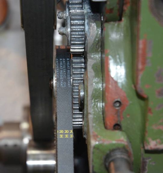
My first thought was to retain the original 127/120 = 1.06 ratio of the gear pair being replaced. That simply meant that the gearbox input pulley needed to have a pitch diameter 1.06 times the pitch diameter of the driving pulley. I made the top pulley from a piece of aluminium out of the scrap box, which seemed about the right diameter (very scientific). I measured the centre distance and calculated the length of belt needed and ordered one. While waiting for that I roughed out the lower pulley. I did not want to fit an idler pulley and the centre distance was fixed, so it was important that the pulley sizes gave a suitable belt tension. To achieve that I intended to finish machine the second pulley when I had the belt. When the belt arrived I offered it up and to my horror it was way to long. I checked the length and it was as marked and as I ordered. I rechecked my calculation which is quite easy. If the pulleys are near the same diameter you average the pulleys' circumferences and add twice the centre distance. My error was that I added the sum of the circumferences not the average. I had the choice of ordering and waiting a week for a new belt or make a larger lower pulley. That would cut all my feed speeds in half. As the highest feed was way higher than any that I would ever use that seemed like it would work well because it would give a lower minimum feed which could be useful for fine finishing. So I went for the larger pulley option but I had to make it from an old steel pulley because I did not have a suitable piece of aluminium. The next photo shows it all assembled and the right hand photo shows the tight lateral spacing. It just fits but I had to thin down the upper concentric pinion to gain enough space.

The small pinions used for direction change spin very fast. These are the two adjacent upper small pinions in the very first photo and the bronze bushes were worn as were the stubs that they ran on. The steel stubs were worn more that the bushes. This combined wear gave some roughness and a lot of noise to the drive, so I reamed out the bushes and made new stubs which eliminated any roughness and reduced noise.
So how does it all work?
Very well. I am pleased with it. Eliminating two gear engagements has further reduced noise, the belt that replaced those is very quiet and the whole system is very smooth. The feed reduction is a bonus that my belt length error demanded. I measured the actual feed over a range of saddle movement of 5" and it came out almost exactly half the feed shown on the table of feeds. It will slow a little due to belt slip when making heavy cuts, but that will be of no consequence. I do not even need to make that 0.5x calculation mentally because the feed steps are binary, i.e. each step up on the coarse selector is double the previous, so I just have to read the next line down on the feed table.
For now I am happy to have my power feeds back, but the thought of ball screws and motors still lingers. Then making a two axis CNC becomes almost trivial, but do I need a CNC lathe? Probably not.


 Reply With Quote


Bookmarks