
 LinkBack URL
 About LinkBacks

A SMALL WINCH FOR SHOP USE
Rather than make yet another video of machines making chips and welders making sparks, I decided to write and show photographs. If you saw my videography ability you would thank me for not sharing it.
There are lots of very reasonably priced lifting devices available for loads from ¼ ton and up. I want a smaller one to safely handle loads up to 150 lb: big lathe chucks, mill vises, rotary tables, welding gas cylinders, etc. The 150 lb is because the things I handle frequently in my shop are all less than 150 lb. I want small and lightweight.
It must incorporate a Weston brake for safe load handling, as is commonly found in chain hoists and boat lifts.
https://nanopdf.com/download/the-wes...-operation_pdf
The load will not fall if the operator releases the crank or hand wheel; it will just stay put. That feature greatly reduces the user strain in operations like mounting a big lathe chuck at arms length. When shoulders are aching and back is screaming from holding that big 4-jaw at arms length trying to get the pegs of the chuck into the holes on the D1-4 lathe spindle without crushing your knuckles on the ways relax! The little winch will bear the weight for you while you swing it and tease it into place.
My light-duty design is simple. I use only one friction material disc, no gears and no splines. The single friction plate (friction material) goes between the friction disc with hex nut and the ratchet disc.
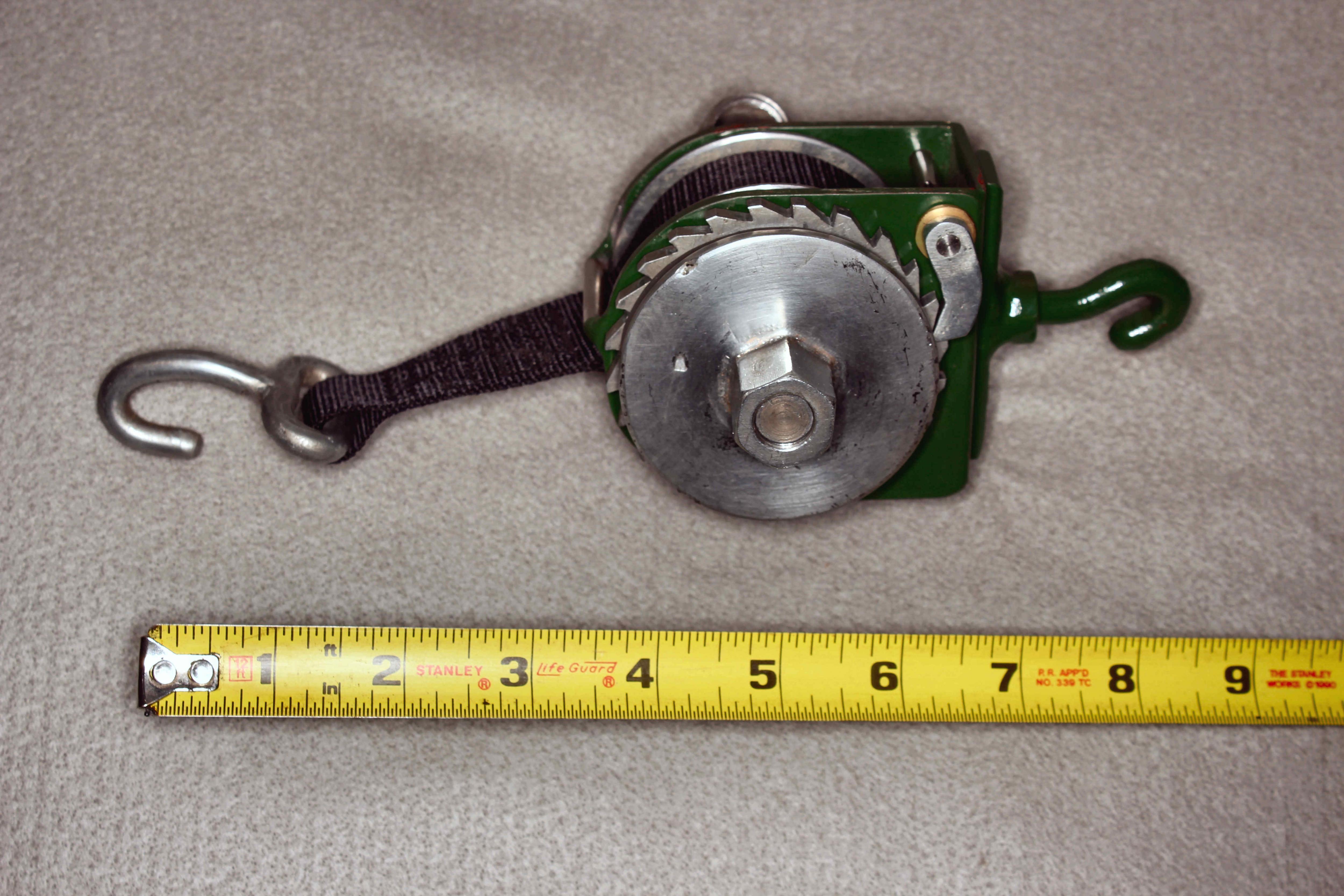
This device weighs less than 2 pounds and is about the size of a baseball. It relies simply on a small diameter spool being operated by a larger-diameter crank. I used 1 wide .043 thick nylon webbing rather than wire rope because webbing is much more flexible and stacks nicely on the spool without jamming up. The webbing I used is rated at 1415 lb breaking strength.
https://www.sailrite.com/1-Black-Lig...-Nylon-Webbing
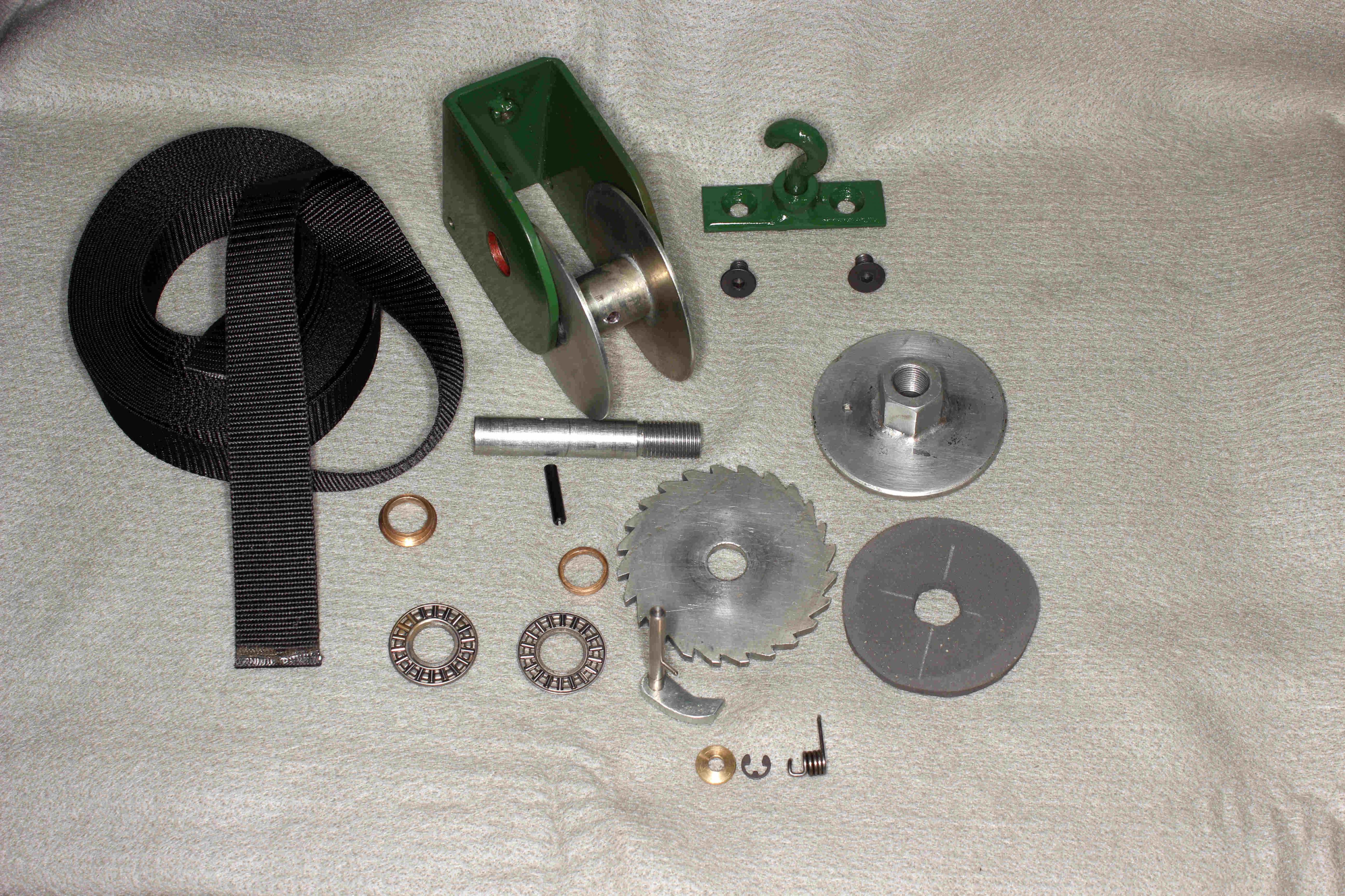
The various parts are shown in the photo below:
This photo omits the load end hook and the web centering guide that I made later. The load hook is held captive to the webbing by many stitches of ordinary carpet thread using a vintage Singer 301 sewing machine.
In operation: when the hex drive is rotated clockwise, if the spool doesnt turn then the threads on the axle draw the drive disc tighter to the friction disc between it and the ratchet disc but the ratchet disc is free to turn clockwise so the axle and spool can also rotate clockwise. The thrust bearings insure free rotation of the spool when the axle is in tension, keeping the spool and the ratchet disc from scraping against the frame.
If there is no torque applied to the drive disc, any downward movement of the load rotates the spool CCW which draw the axle threads tighter, increasing compression of the friction material and hence friction with the ratchet wheel but the ratchet wheel is prevented by the pawl from rotating CCW. Squeeze on the friction disc increases as the screw tightens, increasing friction between friction plate and ratchet disc which cannot turn CCW. When friction torque meets or exceeds load torque, rotation stops. External drive torque is necessary to reach this point, but once it is reached there is zero load torque on the drive nut so no further restraint is necessary.
Rotating the hex drive CCW unscrews the drive disc, reducing friction between drive disc and ratchet disc so the spool can rotate CCW until the threads on the axle again increase friction between drive disc and ratchet disc, which can only rotate clockwise, enough to again stop further CCW rotation of the axle and spool. All credit to Mr. Weston who invented this scheme.
The idea of the ¾ hex drive is so the device can be driven with a variety of devices including open end wrench, ratchet socket wrench, a socket driven by cordless (or corded) drill or a hand wheel with a ¾ socket. The mechanical advantage varies with how much webbing is on the spool. Assuming an 8 radius on the driver, as a ratchet wrench with an 8 handle: with webbing fully deployed mechanical advantage is 19.6 : 1, load moves 2.5 with each revolution and 7.65 lbf of force on the crank is enough to lift 150 lb. With 9 feet of webbing on the spool, the OD is about 2.34 so radius of 1.17 giving a mechanical advantage of 6.84:1 so 7.35 of load movement per revolution (or 0.021 per degree of rotation), with 22 lb of force on the 8 crank enough to lift 150 lb. Thats about 180 in-lbf of torque, well within the capability of most cordless drills.
Here it is assembled and ready to go to work.
The green steel frame is 2.75 wide x 3 high. It is a weldment made of 1/8 mild steel. All unpainted parts are zinc-plated. The spool drum was made from ordinary black iron pipe with OD of 0.814. The sides of the spool are 2.68 dia 14-gage (0.078) steel. The thrust bearings were found on EBay, ten for about $10. The axle is .500 dia, threaded ½-20 on one end. The drive plate (rightmost part) is comprised of a 3/16 thick steel disc brazed to a bit of ¾ hex stock drilled and tapped ½-20. I wanted more length and better threads than are found on hardware store nuts.
The gray friction disc is made of friction material from McMaster Carr. I cut it out freehand with an x-acto knife. The ratchet disc is made of 3/16 HRS. The teeth were cut on a Bridgeport mill using an indexing head and a dovetail cutter. There are 24 teeth 15 degrees apart so a spin index would have sufficed.
The bronze bushings have 0.501 holes and 0.6255 OD, pressed into 0.6250 reamed holes in the frame. The holes look red in the photo because I used a red primer when I painted the frame. After applying green epoxy paint I had to ream out the holes so the bronze bushings would go in.
The bushing that goes on the left has a flange to keep it captive in its hole. The bushing on the right needs no flange because thrust bearings on each side of it keep it captive to the frame. Upon assembly, the axle is pinned to the spool with a roll pin that joins them both axially and rotationally. The webbing is then attached to the spool.
The top (green) hanger hook is free to swivel. I made that a bolt-on rather than just welding to the frame so I can easily change it later if I want to. The pawl was sketched in a 3D solid modeling program (Alibre) and then made freehand of 3/16 HRS (same as the ratchet disc) with belt sander, die grinder and file. The pawl axle is 3/16 dia stainless rod. The little brass washer is the same thickness as the thrust bearing so the pawl will be aligned with the ratchet disc. The little E-clip fits a groove in the pawl axle thats hard to see in the photo.
The pawl spring is shop-made of .032 music wire using a very simple shop-made tool.
I will have ceiling-mounted anchors (lag screw eyes) above the lathe, mill and welding gas cylinders. This could also be the working part of a toolpost-mounted crane like Skyhook, which goes for nearly $1000.
https://tinyurl.com/yhsws567
The Skyhook is rated for 500 lb, far more than I need.


 Reply With Quote


 in the clutch when a load-bearing spool rotates in response to load more than the threa "Pin It")


Bookmarks