-
5 Attachment(s)
Travelling steady
I have never had a travelling steady for my SB lathe and have managed so far without, however I needed to make a longer Acme crosslide feedscrew and the orginal had by now some .033 thou backlash so the time had come to first make a steady.
I have never understood why most lathes have a steady cantilevered over the crosslide mounted on the tailstock side, I tried to fabricate a copy of this but it was not rigid enough.
I decided to make one from ½ inch ms plate and mount it on the chuck side which is pretty much where the tooling is.
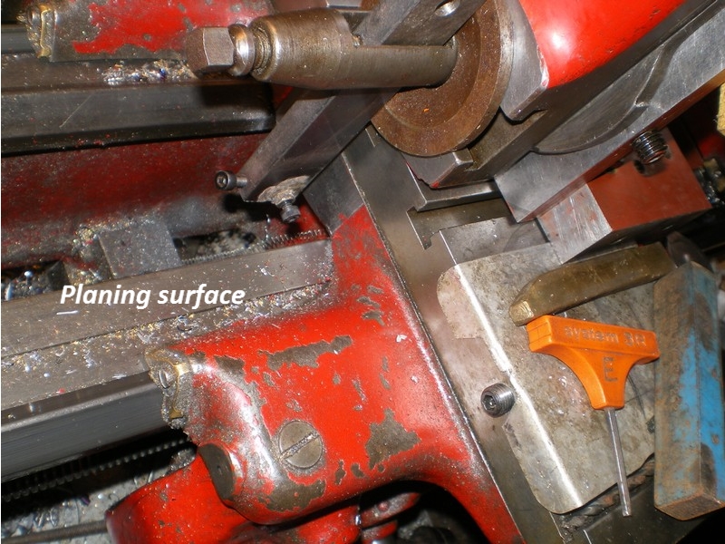
The next problem was an unmachined surface on the saddle to bolt it to so a flat surface was created by using the topslide as a ram mounted vertically on a bracket to plane the surface, I use the topslide for cutting keyways so I already had a lever linkage available.
Attachment 18718
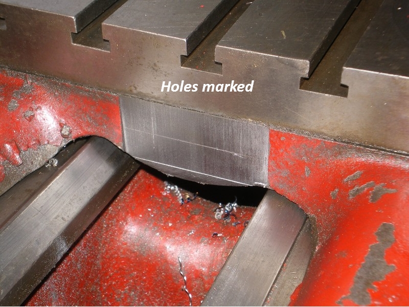
This went very well as cast iron is easy to machine and hole positions were marked out with the same tool to match the originals on the other side of the saddle so it can be used on both sides.
Attachment 18719
So its off with the saddle and drill and tap for two 8mm bolts and a good chance to give it a clean before replacing.
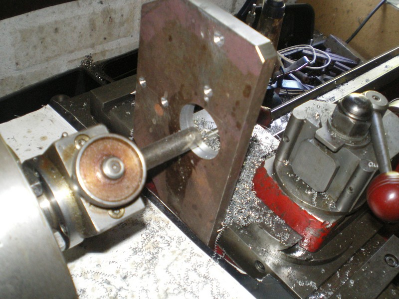
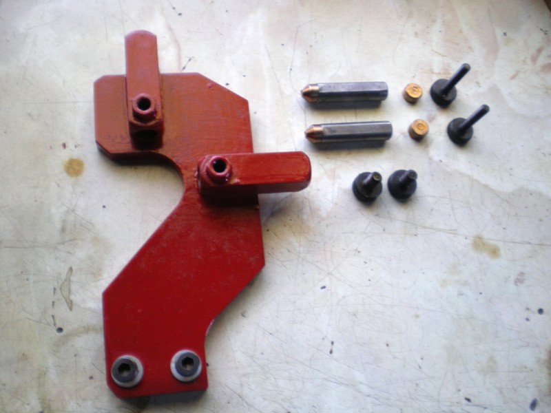
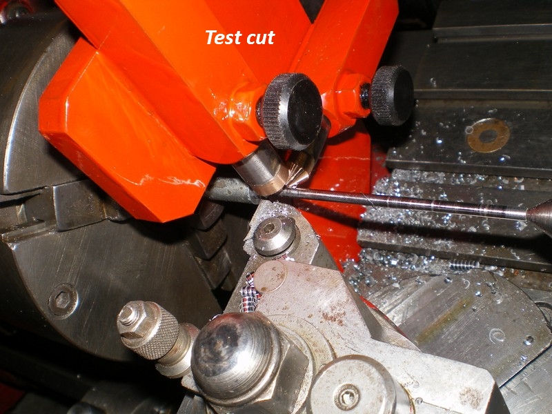
After mounting the prepared and drilled plate a 1.75 inch hole is bored in position and the surplus cut away, the bronze tipped fingers are fitted to square blocks brazed in place with locking finger screws and in this form has proved to be very rigid in use and has enabled me to produce a good 9 inch long feedscrew and two taps to match. With a new bronze nut, backlash is now only .005”, something I can mentally allow for instead of putting pen to paper when indexing.
Attachment 18720
Attachment 18721
By the way I don't have a red paint fetish its just that I have a large qty of red enamel so its use it or lose it.
Attachment 18722
-
Good one. I did mine virtually identical.
-
I would call this a follower rest. Nice job
-
Nice job Olderdan, a very practical way to make it and a perfect finish with the movable heads.:idea:
Have a nice day.
Pierre
-
<!-- BEGIN /var/www/html/homemadetools/protected/modules/zeus/views/tool/postUpdate.php -->
Thanks olderdan! We've added your Traveling Steady to our Lathe Accessories category,
as well as to your builder page: olderdan's Homemade Tools. Your receipt:
<div id="blocks">
<div class="block b1 pngfix">
<div class="bimg">
<div>
<a href="http://www.homemadetools.net/homemade-traveling-steady-2">
<img src="/uploads/201805/homemade-traveling-steady-2.jpeg"/>
</a>
</div>
</div>
<div class="head pngfix"></div>
<div class="left pngfix"></div>
<div class="right pngfix"></div>
<div class="blockover b1 pngfix">
<div class="title">
<a href="http://www.homemadetools.net/homemade-traveling-steady-2">Traveling Steady</a>
<span> by <a href="http://www.homemadetools.net/builder/olderdan">olderdan</a></span>
</div>
<div class="tags">tags:
<a href='http://www.homemadetools.net/tag/steady-rest'>steady rest</a> </div>
</div>
</div>
</div>
<!-- END /var/www/html/homemadetools/protected/modules/zeus/views/tool/postUpdate.php -->
-
Nice approach to a follower rest, especially if you have access (for a reasonable price) to a plasma cutter and thick steel plate.
OK, Marv and you other creative guys. How are we going to make one of these things that adjust the follower shoe in the same amount in the opposite direction as the tool moves in? And remember it has to move only after the cut starts so it won't just crash into the end of the workpiece and mess up everything. OK, you can add tapers to soften the blow. But that's not very elegant.
There has to be a lever or something else to reverse the travel direction and maybe some way to tweak the ratio a bit. And the lever needs to be pretty robust so it won't cause chatter or throw off the accuracy of the cut.
And then there is the "box cutter" approach. Something I've had zero experience with so far but may have to learn sometime in the future. I got one with a bunch of screw machine tooling I bought a while back.
Ed Weldon
-
Ed the whole concept of a traveling rest is to be used either just in front of the cutter or just after the cutter starting the cut near the live center on the stock being turned when turning extremely long shafts I almost always had mine set after the cutter as near to the cut as possible but the one's I had used bearings on the stems. the rests mounted on the cross slide while the cutter was adjusted in with the compound set at zero degree angle. after each successive cut the cross slide was adjusted out while the compound was adjusted in If I made a .200" pass then on the next pass the cross slide would be adjusted out by .200" with any micro adjustment needed made to the stems, then the compound would be adjusted in that much plus the amount of the next cut. But again I might have been working with a 6 to 15" diameter shaft or tube that was as much as 12 ft long
-
Frank - Your approach of using both the compound and the crosslide is great if you have a good machine tool, unlike us hobbyists with somewhat worn equipment. And suggests it may make some sense to spend some serious investment into your compound. I've always done it the old amateur way readjusting the follower with each cut. Ed W
-
Ed I hear ya about the older often worn equipment, with the exception of my 10 year tenor in Kuwait I've always had to buy used older equipment.
the key is to learn where little cheats or the latest buzz word is now days hacks can be used to tighten up the tolerances or how to use those loose worn lead and feed screws to your advantage. I used to have an old lathe made by Something Johnson & sons that had a 16 ft bed or about 14& a half feet between the centers half the teeth were worn off of most of the gears so it only had 2 working spindle speeds the 4 jaw chuck was actually brazed to the spindle I suppose that was because the threads were so wornout that it wouldn't stay tight. I don't know because I never tried to remove it the chuck was 22" in diameter and the jaws without reversing them would open enough to clamp the outside of a 12" 3 jaw Once I got that dialed in I mostly left it there. the ways were so worn that I literally used a grinder to remove .030" along the length before I could even think about trying to true them by scraping Once I got the carriage so it would run smooth /er from end ot end and could rely on less than .010" of vertical movement over the 14 ft of travel I called it good enough Yes I said .010". I had to make a new cross feed nut out of brass then cut it almost in half in the middle then drilled and tapped it for 1/4 20 then used a allen head screw to squeeze the slot this tightened it up on the feed screw I had oil paper shims in the gibs on the cross slide and the compound
the old lathe made cluncky noises the gears were so loose a shop rag could pass through them without being cut up but even with that I used it regularly to turn 12 ft long replacement tubes for 3 ,4 ,5 and 6 stage hydraulic cylinders and thread them on it all because the follow rest did its job.
-
".033 thou backlash" seems pretty tight to me. I'm assuming, of course, that ".033 thou" is meant to mean 0.033 thousandths of an inferial inch - a very small quantity (as opposed to, say, 33 thousandths of such inch - which is a thousand times larger). Very nice work nonetheless.