Thanks trigger, will keep your words in mind.
Chy
Printable View
Thanks trigger, will keep your words in mind.
Chy
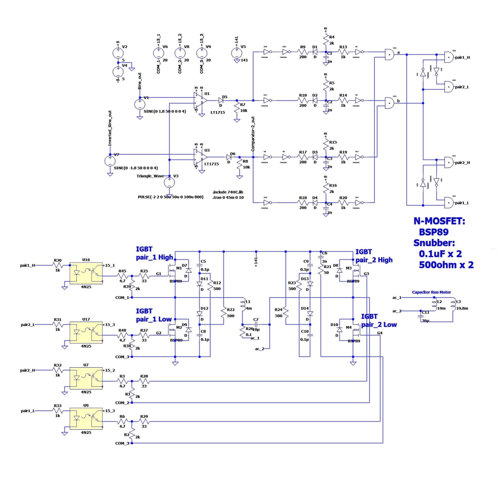
Schematic after the power unit is as follows;
Attachment 36013
showing a LT-spice view, where the triangle, sine wave generators are replaced with a simple built-in parts of LT-spice.
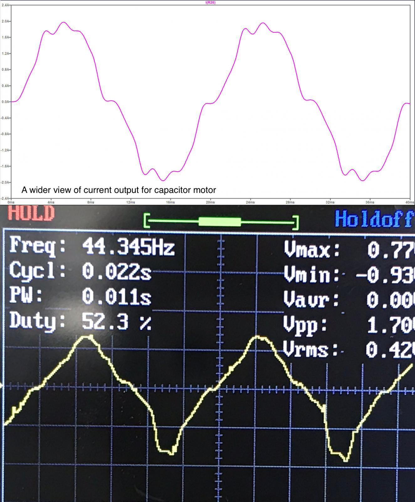
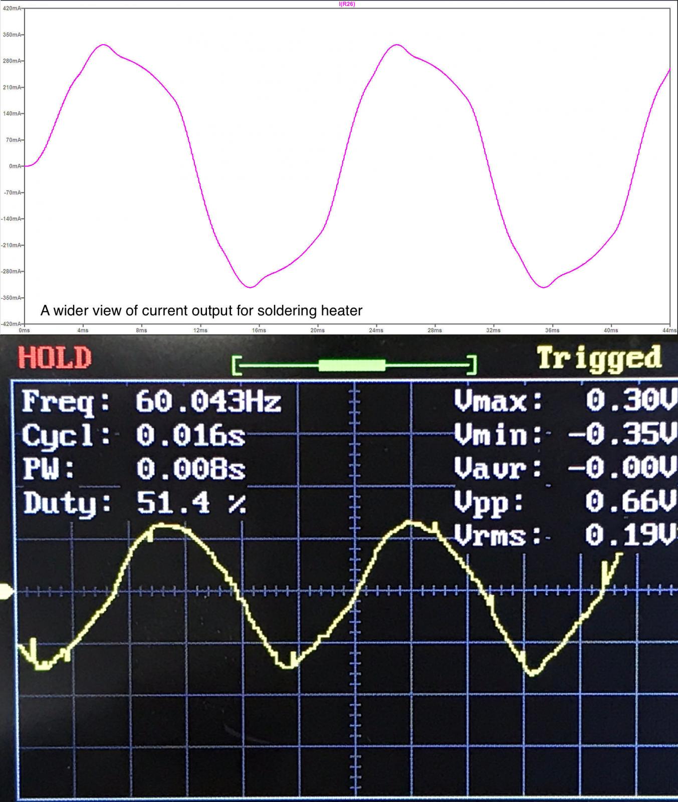
Output wave in LT-spice simulation (red lines), and a couple of real ones (oscilloscope views) here;
Attachment 36014
Attachment 36015
Chy
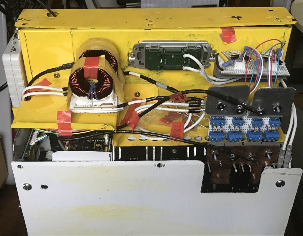
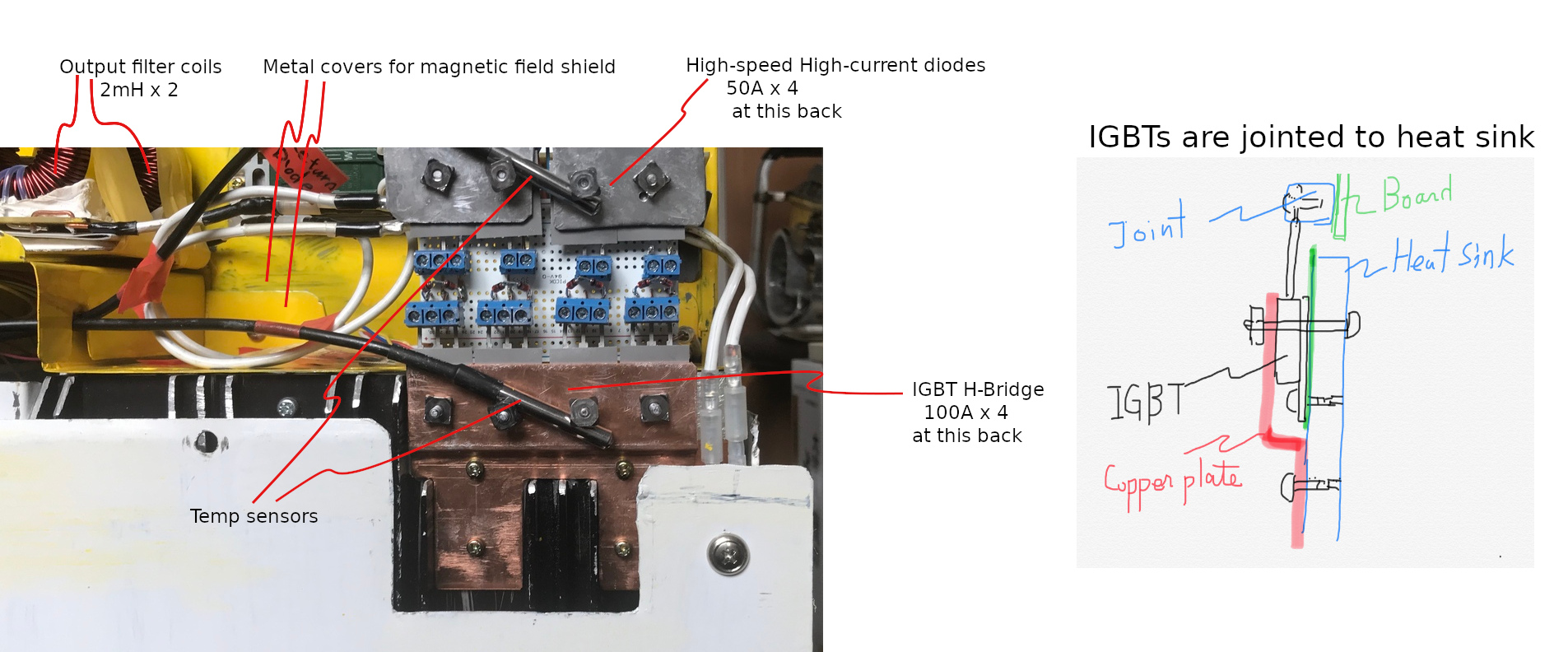
IGBTs, High Speed Diodes, and Output Filter Coils are placed in the metal shield room;
Attachment 36016
Attachment 36017
Chy
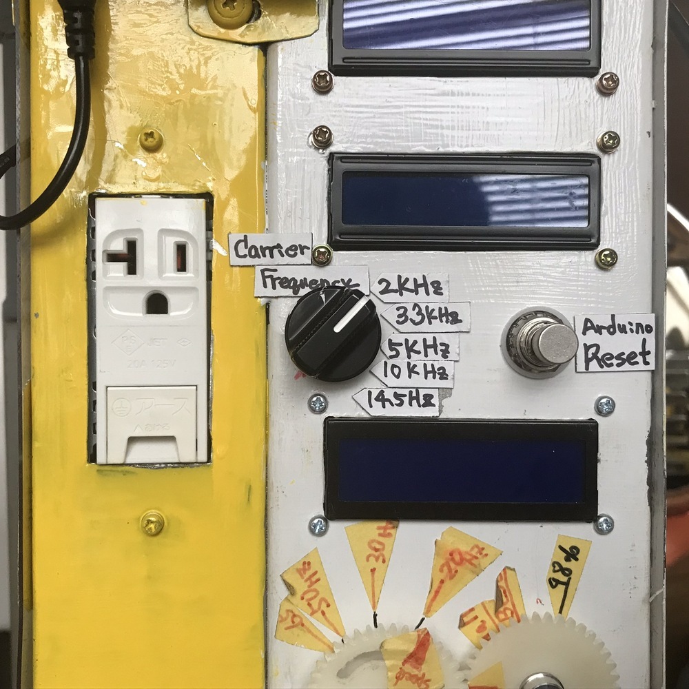
For an observation and study use, I added several kinds of carrier frequencies from 2kHz to 14.5kHz;
Attachment 36018
Chy
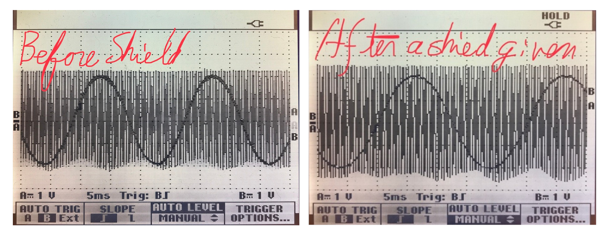
Trigger, I tried to recall my memory and some data on this, and here found a pic showing comparison between the two, before shield and after shield.Quote:
Originally Posted by trigger
Either case bread boards were already replaced with universal boards.
Attachment 36019
Although the carrier wave was not very stable, I know the reason that the center common level was a tad off-set. the thicknesses of the sine waves tell the shield shows effect on it.
This tell us that even PCB board wants some means for cutting noise.
Chy
Shoot me your code. I can have a look at it if you want. Are you bit-banging the Arduino functions? Interrupts and PWM outputs are very, very nice when you get them set up. If you swapped the three Arduino Unos out for one Arduino Due you can definitely monitor current, frequency and temperature with a single board, but you could probably also generate your sine waves. Arduino Dues are very fast. There are also lots of other (and much faster) boards to choose from as well. If you're having frequency and noise issues driving it directly from a microcontroller might solve some oscillator problems.Quote:
Originally Posted by chy_farm
Again, awesome project and great work.
Nova, thank you very much for your kindness.Quote:
Originally Posted by nova_robotics
This information is very big for me, for years I have been learning C, but not yet graduate from a first grade though, lol.
When I got to know Arduino, was a bit disappointed that it uses C++, which uses 'Class', this makes me mixed up and still I am loosing my way to restart learning.
So this offer is very great to me! Perhaps you make me stand again and start again Nova. Will try posting the code and ask you for your information.
Many thanks!!
Chy
Hi Chy-Farm, Thanx for this extensive communication. Now I am curious about the IGBT circuit. And is 100V the standard grid voltage in Japan?
regards, Carnel
Hi Carnel, yes! It's as low as 100V, lol. This makes us sometimes frustrated though.Quote:
Originally Posted by Carnel
Chy
<!-- BEGIN /var/www/html/homemadetools/protected/modules/zeus/views/tool/postUpdate.php -->
Thanks chy_farm! We've added your Factory Fan VFD to our Electronics category,
as well as to your builder page: chy_farm's Homemade Tools. Your receipt:
<div id="blocks"> <div class="block b1 pngfix"> <div class="bimg"> <div> <a href="https://www.homemadetools.net/homemade-factory-fan-vfd"> <img src="/uploads/234794/homemade-factory-fan-vfd.jpeg"/> </a> </div> </div> <div class="head pngfix"></div> <div class="left pngfix"></div> <div class="right pngfix"></div> <div class="blockover b1 pngfix"> <div class="title"> <a href="https://www.homemadetools.net/homemade-factory-fan-vfd">Factory Fan VFD</a> <span> by <a href="https://www.homemadetools.net/builder/chy_farm">chy_farm</a></span> </div> <div class="tags">tags: <a href='https://www.homemadetools.net/tag/fan'>fan</a>, <a href='https://www.homemadetools.net/tag/controller'>controller</a> </div> </div> </div> </div>
<!-- END /var/www/html/homemadetools/protected/modules/zeus/views/tool/postUpdate.php -->