Free 186 More Best Homemade Tools eBook:  
Get 2,000+ tool plans, full site access, and more.

User Tag List

Page 1 of 3 1 2 3 LastLast
Results 1 to 10 of 21

Thread: Watchmakers lathe cross sllide

  1. #1
    Britannicus's Avatar
    Join Date
    Jan 2017
    Posts
    12
    Thanks
    1
    Thanked 5 Times in 4 Posts

    Britannicus's Tools

    Watchmakers lathe cross sllide

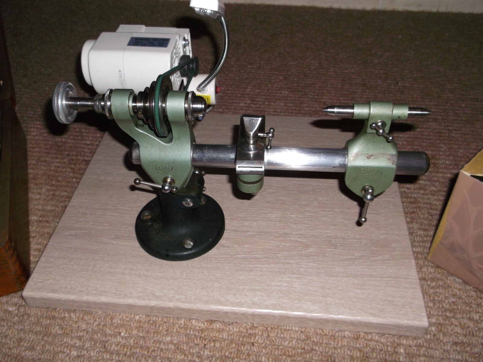
    A new project to add to my watchmaker's lathe

    this has a D cross section slide (see pic) Watchmakers lathe cross sllide-aa.-pultra.jpg


    Unfortunately I have not got a tool post or cross slide for this lathe - and to buy them (if you can find one) is an eye watering expense, so I've decided to make one. Now for some here, my approach may seem crude, but I'm a newbie with limited tools and skills, so I thought I'd share my approach for your thoughts and constructive (I hope) criticism - now first point is this doesn't have to be strong, but has to provide quite fine adjustments - I have chosen aluminium simply for ease of working.

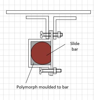
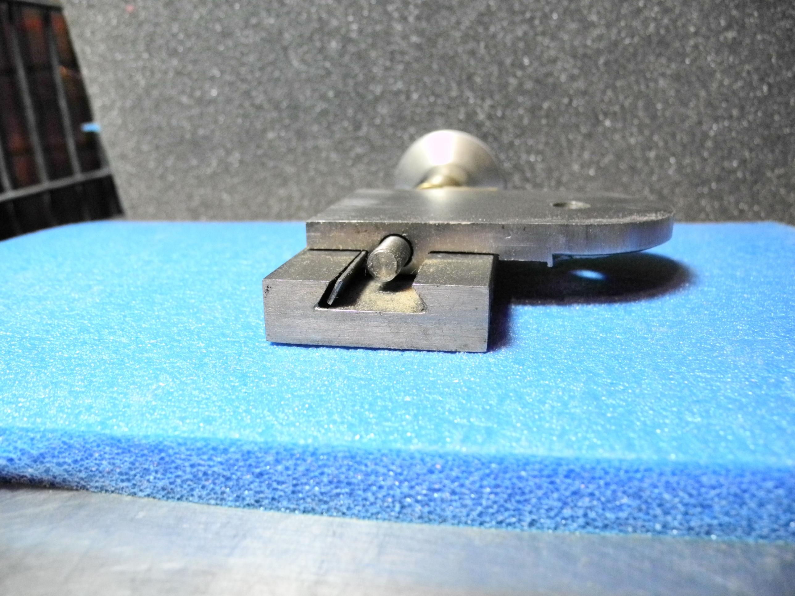
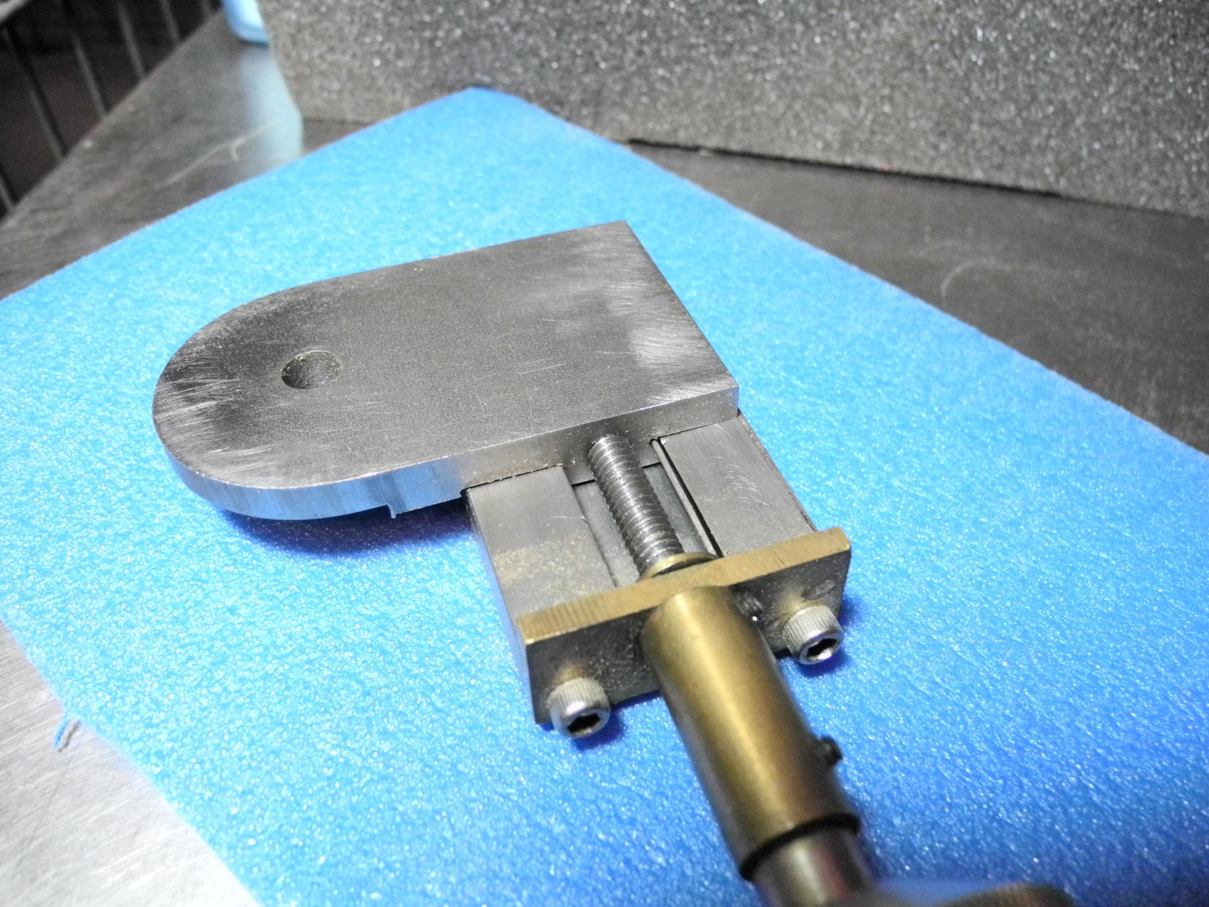
    My first problem is to manufacture a bracket to sit on that D-shaped slide which won't damage it, that will slide and can be clamped but that I can make easily. This also needs to provide a firm base.

    To do this I'm falling back on my robotics experience and using polymorph. I don't see much discussion of it here, but in robots it's very common. For those that don't know it's a plastic with the attributes of nylon and a melting point of 700C, which means it casts very precisely and you can mould to anything. The plan is to make a box section, then to fill the intervening space with semi molten polymorph - the bar being cold and oiled will prevent it sticking to the bar and cause a really tight fit. My hope is that this should provide me with a strong fixture which when solid will slide smoothly along the bar (see pic)

    Watchmakers lathe cross sllide-slide-bracket.jpg

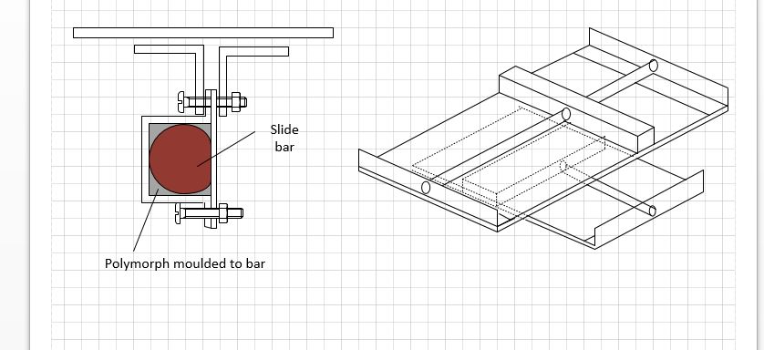
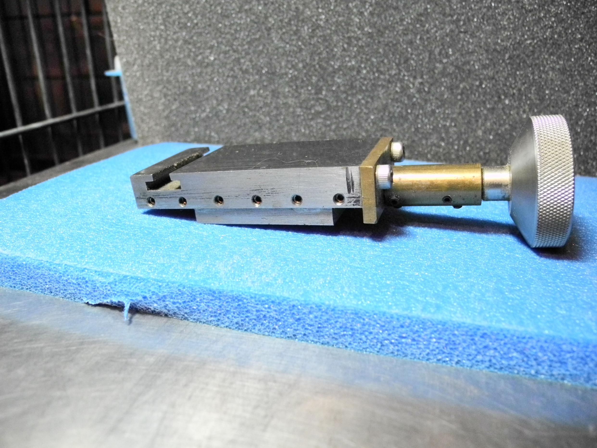
    finally I intend to create 2 slides made from tapped aluminium bar which can then be moved back and forth on a bed by means of an M6 threaded bar - this should provide me with precision to 1mm per turn to the bar (see picture. these will be mounted one on the box section on the bar, and the second on the slide bar of the first at right angles.

    Watchmakers lathe cross sllide-x-slide.jpg

    I have yet to commence building, but these are my rather amateur sketches - your thoughts would be appreciated.

    186 More Best Homemade Tools eBook

  2. #2
    ChrisB257's Avatar
    Join Date
    Dec 2016
    Posts
    19
    Thanks
    15
    Thanked 15 Times in 7 Posts

    ChrisB257's Tools
    Hi,
    Basically I'd say your approach is probably the simplest, without having to do some quite fiddly machining from solid. I am familiar with the polymorph and that could work OK as described. Re a thread - am thinking, if you could go to inch threads, then a 20 pitch would give you 50 thou per revolution, which divides up nicely - but if you only want to be metric then I guess the 1mm pitch would do just fine - that would divide easily into 1/10s or better (one rev of that would equate to .039").
    Ahh yes as has now been mentioned, backlash will be a potential factor. Either split nuts or, some means of applying a permanent spring tension.
    Best of luck. Chris.

    2000 Tool Plans
    Last edited by ChrisB257; Feb 3, 2017 at 01:53 PM.
    Ain't technology great - until it goes wrong!
    The Old Man's Shop

  3. The Following User Says Thank You to ChrisB257 For This Useful Post:

    Paul Jones (Feb 7, 2017)

  4. #3

    Join Date
    Feb 2016
    Posts
    7
    Thanks
    7
    Thanked 6 Times in 4 Posts
    Some thoughts......you will want to deal with backlash early in your design. You could use a split and adjustable nut or two opposing nuts or maybe even some sort of spring affair. You are on the right track, good luck!
    Bob W.

  5. #4
    Supporting Member ncollar's Avatar
    Join Date
    Oct 2012
    Posts
    354
    Thanks
    23
    Thanked 180 Times in 126 Posts
    Britannicus
    I tried to gather information on building my own cross slide. I tried on several sites and had no replies except I would need a lot of machinery to do so. I am not a quitter and it may be on the back burner but I will build a cross slide for my 8 mm lathe. Yours is a 6 mm which means it is a little bit smaller. Look at all the different cross slides and draw on and build it. I can not see paying 7 hundred or better. I can make a lot of stuff with $500 worth of fine grained cast iron. Maybe we can collaborate on a design together.
    Good Luck

  6. #5

    Join Date
    Nov 2016
    Posts
    11
    Thanks
    13
    Thanked 7 Times in 4 Posts
    IF you have access to a milling machine, then producing a serviceable cross slide is not horribly difficult. Use 60 degree dovetail cutters for the slides and be sure to leave sufficient width for a gib on one side of the moving element. For a watchmaker's lathe I recommend a 40 pitch leadscrew on both axes for a 25 mil/revolution control handle. While it is possible to make a cross slide with near zero backlash, in practical terms it is not worth the effort. Make the leadscrew nut out of sintered bronze to reduce wear. Horizontal travel should be about 3 inches and cross feed at least two inches. The entire cross slide assembly can be adjusted on both axes by loosening the bed clamp, so a lot of cross slide travel is not necessary. Leadscrew diameters should be close to 1/4 inch, Specialty 1/4 taps and dies for a 40 tpi pitch are readily available in this diameter. Check online for drawings of the Levin jewelers lathe cross slides to get a better idea of construction. Good Luck!!

  7. The Following User Says Thank You to Iconoscope For This Useful Post:

    Paul Jones (Feb 7, 2017)

  8. #6

    Join Date
    Dec 2016
    Posts
    3
    Thanks
    0
    Thanked 0 Times in 0 Posts
    Well Brittanicus, my experience in making a crosslide has been limited to the conventional cast iron. But I will defer to your experience with polymorph. Designing in some adjustment for play seems to be a good idea as is some solid clamping arrangement. Feed screw pitch is your choice and a 1MM module combined with a 40 or 50 division wheel should give you an adequate range of divisions but be sure and include an adjustment of play for the nut. Can you mold the crosslide dovetail in polymorph as a monolithic unit? Then address the construction of the moving table in brass, iron, or polymorph. Remember that a large volume of a flexable material can replace a smaller volume of a more rigid material. Only on the mounting surface for the toolholder might you need a molded in surface like a machined hard washer. Good luck with this project and be sure to post your results! Bill in Boulder CO USA

  9. #7

    Join Date
    Nov 2016
    Posts
    11
    Thanks
    13
    Thanked 7 Times in 4 Posts
    IF you have access to a milling machine, then producing a serviceable cross slide is not horribly difficult. Use 60 degree dovetail cutters for the slides and be sure to leave sufficient width for a gib on one side of the moving element. For a watchmaker's lathe I recommend a 40 pitch leadscrew on both axes for a 25 mil/revolution control handle. While it is possible to make a cross slide with near zero backlash, in practical terms it is not worth the effort. Make the leadscrew nut out of sintered bronze to reduce wear. Horizontal travel should be about 3 inches and cross feed at least two inches. The entire cross slide assembly can be adjusted on both axes by loosening the bed clamp, so a lot of cross slide travel is not necessary. Leadscrew diameters should be close to 1/4 inch, Specialty 1/4 taps and dies for a 40 tpi pitch are readily available in this diameter. Check online for drawings of the Levin jewelers lathe cross slides to get a better idea of construction. Good Luck!!

    Here is a top slide I made a few years ago for a Unimat lathe.

    Watchmakers lathe cross sllide-dscn1753p.jpgWatchmakers lathe cross sllide-dscn1754p.jpgWatchmakers lathe cross sllide-dscn1755p.jpg

  10. The Following User Says Thank You to Iconoscope For This Useful Post:

    Paul Jones (Feb 7, 2017)

  11. #8

    Join Date
    Dec 2016
    Location
    east tawas mi.
    Posts
    4
    Thanks
    0
    Thanked 1 Time in 1 Post

    BRITANNICUS COMPOUND CROSSFEED FOR WATCHMAKER LATHE

    BRITANNICUS I ONCE ALMOST BOUGHT ONE OF THESE SIMILAR TO YOURS, IT WAS MADE BY ELGIN AND HAD THE SAME ISSUE. AS IT TURNED OUT BY THE TIME I REPLIED TO THE AD IN CRAIGSLIST IT HAD BEEN SOLD FOR $150 INLUDING COMPLETE SET OF COLLECTS. ANYWAY I HAD AN IDEA I GOT FROM MY LITTLEMACHINE SHOP.COM CATALOG NUMBER 23. ON PAGE 57 PART NUMBER 1769 COMPLETE COMPOUND REST ASSEMBLY FOR A MINI LATHE I.E. 7X14 7X10 12 ECT. THIS WAY YOU WOULD HAVE THE HARD PART DONE, AND I BELIEVE THE MOUNT COULD BE BUILT FOR NEXT TO NOTHING. IT WOULD SIMPLY SLIDE, AND COULD LOCK ONTO THE TUBE. THIS UNIT SELL'S FOR $72.95 COMPLETE! AT LEAST GET THIS CATALOG, AND LOOK IT OVER, IV'E USED THEM IN THE PAST. THE QUALITY IS VERY DECENT, AND THEIR PRICES ARE SINFULLY LOW!! THESE ARE GOOD PEOPLE TO DEAL WITH, AND ALL THEY DEAL IN IS MINI AND MICRO PARTS AND ASSESSORIES. GOOD LUCK TO YOU! AND YOUR BEAUTIFUL LITTLE MACHINE "CHARSAND"

  12. #9

    Join Date
    Mar 2015
    Posts
    43
    Thanks
    0
    Thanked 18 Times in 12 Posts
    Lots of food for thought in these posts. The $72 ready-made cross slide mentioned by charsand looks like a good deal.

    It's not clear to me what the "D" shaped element you mention is. Is it the main bed bar?

    I was interested to learn about polymorph, which I had never heard of before, but I could not find in a quick search any properties other than melting temp and how remarkably strong it is claimed to be. No info on modulus of elasticity, coefficient of thermal expansion, etc. But I would be extremely surprised if such a product had anywhere near the desirable properties available in epoxy resins, especially with an appropriate filler material. I recommend you research the myriad available epoxies.

    The extreme simplicity of using polymorph fades in significance compared with getting the optimum properties (rigidity, lubricity, precision of casting, etc.). And epoxies are as easy to use and much more versatile than polymorph, if somewhat messy.

    I cast a follower nut out of clear epoxy resin (West Systems 105/206) for a precision lead screw on a gearhead motor for which no nut was available from the motor vendor (All Electronics in VanNuys, California) and the result was very satisfactory with zero apparent backlash. (Backlash was not a concern in my case since this was for a simple actuator, not a precision slide.) The vital aspect of using epoxy for such an application is, of course, achieving total coverage of the screw (or bar) in the region to be replicated with a suitable release agent. As I recall, for my follower nut I thoroughly greased the lead screw with a heavy silicone grease, then wiped most of the excess grease off, but not aggressively and, of course, not using solvents. Worked great. I had to apply a bit of torque (by hand) to initially break the cast nut loose from the lead screw but now if follows nicely with a bit of drag indicating, I believe, a very close tolerance fit. Don't know about longevity of the fit, but suitable for my application.

    Of course, epoxy will only work in this type of application if the lead screw or bar is uniform and very smooth because the epoxy replicates every pit and irregularity of the mold down to the finest detail and, therefor, will bind on any rough surface.

  13. #10

    Join Date
    Mar 2015
    Posts
    43
    Thanks
    0
    Thanked 18 Times in 12 Posts
    One additional comment on your original concept drawing, Britannicus. You show the slide base plate connected to the cast slide by means of a bolt through a flange on the "U" section where it abuts the bottom plate. This is a weak connection since it relies on only the bending strength of that connection. Using two flat plates on each side of the "D" bar and connecting the slide base plate to the two side plates will provide much greater rigidity of the system. You could also just use two "L" sections as the side plates and two rectangular bars for the top and bottom closures of the casting area and eliminate the bolted joint.

Thread Information

Users Browsing this Thread

There are currently 1 users browsing this thread. (0 members and 1 guests)

Bookmarks

Posting Permissions

  • You may not post new threads
  • You may not post replies
  • You may not post attachments
  • You may not edit your posts
  •