Free 186 More Best Homemade Tools eBook:  
Get 2,000+ tool plans, full site access, and more.

User Tag List

Page 1 of 2 1 2 LastLast
Results 1 to 10 of 19

Thread: Welding Pulse Monitor

  1. #1
    Supporting Member chy_farm's Avatar
    Join Date
    Apr 2018
    Location
    Yokohama, Japan
    Posts
    125
    Thanks
    65
    Thanked 211 Times in 60 Posts

    chy_farm's Tools

    Welding Pulse Monitor

    I haven't ever seen real welding wave forms either in direct current welding for steel sheets or alternative current for aluminium, magnesium.
    if I was able to see them it should be informative in determining several important setting values.

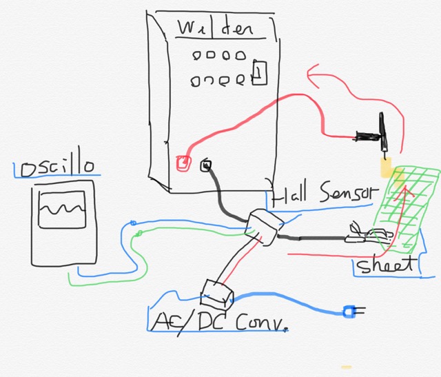
    So I tried to set up a current detector added to my welder, by applying a hall effect sensor unit being sold on the market, at around the ground cable of my old analogue welder.

    Welding Pulse Monitor-welding_current_sensor_.jpg

    Red curves with arrows tell how welding current goes while the arc melts metal, it might sound funny to you since the arc emits out of the torch yet the current runs to the adverse direction. This is why in TIG welding the welder uses minus electrons coming out of the torch while giving heat to the spot, so the polarity of this torch should be minus and the ground (or the metal to be melted) are plus.

    186 More Best Homemade Tools eBook

  2. The Following 10 Users Say Thank You to chy_farm For This Useful Post:

    baja (Jul 29, 2020), bigbobcohen (Jul 28, 2020), Carnel (Jul 29, 2020), DIYer (Jul 28, 2020), dubbby (Jul 29, 2020), Jon (Jul 27, 2020), nova_robotics (Apr 6, 2022), rlm98253 (Jul 28, 2020), Sleykin (Jul 29, 2020), Tonyg (Jul 29, 2020)

  3. #2
    Supporting Member chy_farm's Avatar
    Join Date
    Apr 2018
    Location
    Yokohama, Japan
    Posts
    125
    Thanks
    65
    Thanked 211 Times in 60 Posts

    chy_farm's Tools
    The purpose is to further optimize my old analogue welder, welding current and welding wave forms when she has to weld thin aluminium sheets in butt-joint.

    With my novice skill job of butt-joint with thin aluminium (like ones with 1.5mm thick) has been a tiny thorn in the throat. For one thing aluminium filler did not want to melt in to the starting welding pools when I have to weld both ends of the two sheets at several intervals, especially in welding this thinner alu sheets.

    I know pros can do it better, but it's not about myself, so tried to find another way to make it better, and found one called the MIX-TIG, a way to generate alternative current for thinner aluminium while mixing some percentages of direct current to the aiming target.
    Anyways this should be posted on another thread soon after this.

    The composition is like this;
    Welding Pulse Monitor-welding_current_sensor_-0-.jpg
    .
    We need some handy oscilloscope one like this;
    Welding Pulse Monitor-welding_current_sensor_-2-.jpg

    2000 Tool Plans
    Last edited by chy_farm; Jul 27, 2020 at 08:45 PM.

  4. The Following User Says Thank You to chy_farm For This Useful Post:

    nova_robotics (Apr 6, 2022)

  5. #3
    Supporting Member chy_farm's Avatar
    Join Date
    Apr 2018
    Location
    Yokohama, Japan
    Posts
    125
    Thanks
    65
    Thanked 211 Times in 60 Posts

    chy_farm's Tools
    This hall sensor is named HAS-50, which allows to detect current up to 50 amperes, and is made in USA.
    Welding Pulse Monitor-welding_current_sensor_-1-.jpg
    I thought it only detects current below 50A, but found it can do good job either for current above 50A.

  6. #4
    Supporting Member chy_farm's Avatar
    Join Date
    Apr 2018
    Location
    Yokohama, Japan
    Posts
    125
    Thanks
    65
    Thanked 211 Times in 60 Posts

    chy_farm's Tools
    Showing an oscilloscope view of an analogue wave form consists of 12.5% (this percentage is called "duty ratio") pulses when i did a DC welding with the pulse switch ON, to a sample steel sheet.
    .
    Welding Pulse Monitor-dctig_analogue_10hz_minimum-duty_100a-5a.jpg
    .
    The pulses come downward to reach nearly -8.1V in this view, but we have to calculate the real amperage by making it 10 times, and replace the unit form volt to ampere, so this means the peak welding amperage is minus 81 amperes.

  7. The Following User Says Thank You to chy_farm For This Useful Post:

    that_other_guy (Oct 18, 2022)

  8. #5
    Supporting Member chy_farm's Avatar
    Join Date
    Apr 2018
    Location
    Yokohama, Japan
    Posts
    125
    Thanks
    65
    Thanked 211 Times in 60 Posts

    chy_farm's Tools
    For a better comprehension, gave a small modification to the view above, added the wave-form-layers to see the current going further;
    .
    Welding Pulse Monitor-dctig_analogue_10hz_minimum-duty_100a-5a_mod.jpg
    .
    We can only melt steel sheet with the 'Welding Current' of the pulse, while we make repose when the pulse is off.
    This repose-period when the pulse is off, we call the current of this period 'Base Current'.

    Thinner sheet are easy to be melt-down, so we beginner love to use this trick, melt the target in short period, then make repose to cool the target down for a while, and repeat and repeat.

  9. #6
    Content Editor
    Supporting Member
    DIYer's Avatar
    Join Date
    Aug 2013
    Posts
    3,056
    Thanks
    772
    Thanked 1,852 Times in 1,653 Posts


    Thanks chy_farm! We've added your Welding Pulse Monitor to our Electronics category,
    as well as to your builder page: chy_farm's Homemade Tools. Your receipt:


  10. The Following User Says Thank You to DIYer For This Useful Post:

    chy_farm (Jul 29, 2020)

  11. #7

    Join Date
    Jul 2019
    Location
    Ohio, USA
    Posts
    170
    Thanks
    200
    Thanked 96 Times in 49 Posts
    Quote Originally Posted by chy_farm View Post
    This hall sensor is named HAS-50, which allows to detect current up to 50 amperes, and is made in USA.
    Click image for larger version. 

Name:	welding_current_sensor_(1).jpg 
Views:	176 
Size:	109.3 KB 
ID:	35936
    I thought it only detects current below 50A, but found it can do good job either for current above 50A.
    Pretty nice project. Thank you for sharing. I thought that sensor looked familiar. The maker of that sensor used to be the parent company of my work.

    Cheers!

  12. The Following User Says Thank You to FEM2008 For This Useful Post:

    n9dug (Jul 29, 2020)

  13. #8
    Supporting Member
    Join Date
    Sep 2018
    Location
    Groningen, NL
    Posts
    44
    Thanks
    318
    Thanked 32 Times in 11 Posts

    Carnel's Tools
    Hi Chy_Farm,
    Your post is very interesting so thanx for it. I have a question. You mentioned you are using an old analogue welder. Perhaps I am wrong but my idea of an analogue welder is a welding transformer with large and adjustable spreading inductance to limit the welding current. But how are the pulses created? These 13 msec pulses with small rise and fall times need a semiconductor to switch these pulses on and off. Can you please tell something more about this "old analogue welder"? Or should I better wait for your following post?

  14. #9
    Supporting Member tonyfoale's Avatar
    Join Date
    Nov 2016
    Location
    Spain
    Posts
    1,557
    Thanks
    686
    Thanked 2,643 Times in 708 Posts

    tonyfoale's Tools
    I was about to ask the same as Carnel.
    By analogue do you mean that the controls are separate rotary knobs rather than stepwise control by button presses.

  15. #10
    Supporting Member chy_farm's Avatar
    Join Date
    Apr 2018
    Location
    Yokohama, Japan
    Posts
    125
    Thanks
    65
    Thanked 211 Times in 60 Posts

    chy_farm's Tools
    Carnel and tonyfoale, good evening.

    Thank you for having interests on my project. Since I am a beginner in electronics and still learning things by books and internet pro-sites, I may be wrong either, but anyways I am going to try to show what I know about my old analogue welder.
    Posting an image map to illustrate my understanding below, but as far #6 I am yet on the way learning it, so I may not be able to give good replay on this.

    > By analogue do you mean that the controls are separate rotary knobs rather than stepwise control by button presses.

    You'r right Tony,

    Welding Pulse Monitor-pwm_image.jpg

    Chy

    p.s. I see an image below which I tried to delete, was not able to...
    p.p.s. Was able to do it.
    Last edited by chy_farm; Jul 29, 2020 at 07:18 PM.

  16. The Following 3 Users Say Thank You to chy_farm For This Useful Post:

    Carnel (Jul 30, 2020), Sleykin (Jul 29, 2020), that_other_guy (Oct 18, 2022)

Thread Information

Users Browsing this Thread

There are currently 1 users browsing this thread. (0 members and 1 guests)

Bookmarks

Posting Permissions

  • You may not post new threads
  • You may not post replies
  • You may not post attachments
  • You may not edit your posts
  •