Free 186 More Best Homemade Tools eBook:  
Get 2,000+ tool plans, full site access, and more.

User Tag List

Page 1 of 2 1 2 LastLast
Results 1 to 10 of 11

Thread: $7 Smart Component Tester (LCR-T4 M328)

  1. #1
    Supporting Member tsbrownie's Avatar
    Join Date
    Feb 2019
    Posts
    171
    Thanks
    123
    Thanked 323 Times in 100 Posts

    tsbrownie's Tools

    $7 Smart Component Tester (LCR-T4 M328)

    If you deal with electronics for work or hobby, this is something to have! They are cheap $6-$7, but come with no instructions.


    Got one of those smart component testers: resistors, capacitors, transistors, MOSFETs, diodes, ... Testing the tester.


    WARNING: There is always a danger of shock, fire and electrocution when working with electricity. Capacitors of high voltage can kill if mishandled.

    186 More Best Homemade Tools eBook

  2. The Following 3 Users Say Thank You to tsbrownie For This Useful Post:

    FEM2008 (Dec 20, 2019), jimfols (Dec 20, 2019), mklotz (Dec 20, 2019)

  3. #2
    Supporting Member mklotz's Avatar
    Join Date
    Aug 2015
    Location
    LA, CA, USA
    Posts
    3,434
    Thanks
    357
    Thanked 6,380 Times in 2,117 Posts

    mklotz's Tools
    I have to get one of those! I have a huge stockpile of components salvaged from old equipment and passed to me by folks retiring from the hobby. Identifying and testing it to select what I need is an eye-watering task.

    I don't like to deal with Ebay or Bangood and the other Chinese-direct shippers but I see that the unit is available from Amazon...

    https://www.amazon.com/Multifunction...J6JE19EAC96R9G

    for $ 15.50 so it's on my shopping list.

    2000 Tool Plans
    ---
    Regards, Marv

    Home Shop Freeware
    https://www.myvirtualnetwork.com/mklotz

  4. The Following 3 Users Say Thank You to mklotz For This Useful Post:

    baja (Dec 21, 2019), Toolmaker51 (Dec 21, 2019), tsbrownie (Dec 20, 2019)

  5. #3
    Supporting Member tsbrownie's Avatar
    Join Date
    Feb 2019
    Posts
    171
    Thanks
    123
    Thanked 323 Times in 100 Posts

    tsbrownie's Tools
    FYI: There is another style that has a digital selector. This one in this video is faster and easier. The selector type has calibration (and a basic freq gen, and freq counter). Either and both are better than doing lookups or using scopes, freq gens and standard parts to find values.

  6. The Following User Says Thank You to tsbrownie For This Useful Post:

    Toolmaker51 (Dec 21, 2019)

  7. #4
    Supporting Member baja's Avatar
    Join Date
    Dec 2017
    Posts
    249
    Thanks
    7,599
    Thanked 81 Times in 59 Posts

    baja's Tools
    Quote Originally Posted by mklotz View Post
    I have to get one of those! I have a huge stockpile of components salvaged from old equipment and passed to me by folks retiring from the hobby. Identifying and testing it to select what I need is an eye-watering task.

    I don't like to deal with Ebay or Bangood and the other Chinese-direct shippers but I see that the unit is available from Amazon...

    https://www.amazon.com/Multifunction...J6JE19EAC96R9G

    for $ 15.50 so it's on my shopping list.
    Would that unit be able to diagnose a digital clock? I have a clock that came out of an old Marlboro advertising sign from a Circle K store in the mid 80`s that I set in a brass housing. It worked for years and years and one day started blinking like the power had shut down. Took it to a guy I know that fixes electronics and he had it for a couple months and it didn`t malfunction. I brought it home and found a loose connection in the cord which I repaired and it worked fine for a couple more months and the same thing. I can plug it in and it will run for a while and back to the same old, same old. I want to repair it because it`s the only clock I found that I can see at night with my glasses off, lol. Unless I spend big money on a new one.

  8. The Following User Says Thank You to baja For This Useful Post:

    tsbrownie (Dec 22, 2019)

  9. #5
    Supporting Member metric_taper's Avatar
    Join Date
    Mar 2017
    Location
    Marion, Iowa
    Posts
    585
    Thanks
    227
    Thanked 257 Times in 153 Posts

    metric_taper's Tools
    Quote Originally Posted by baja View Post
    Would that unit be able to diagnose a digital clock? I have a clock that came out of an old Marlboro advertising sign from a Circle K store in the mid 80`s that I set in a brass housing. It worked for years and years and one day started blinking like the power had shut down. Took it to a guy I know that fixes electronics and he had it for a couple months and it didn`t malfunction. I brought it home and found a loose connection in the cord which I repaired and it worked fine for a couple more months and the same thing. I can plug it in and it will run for a while and back to the same old, same old. I want to repair it because it`s the only clock I found that I can see at night with my glasses off, lol. Unless I spend big money on a new one.
    No, it will test components that are removed from the circuit. Sounds like it is a power supply problem. I'm guessing this clock uses 5VDC logic. You can either figure out what is wrong with the supply, or replace it with a AC mains to low volt supply brick. Does the printed wiring board have any silk screen legends that indicate voltage? I don't know what your electronic skills are.

    They do make a model of this, that has a boost supply that can test Zener diodes to 30v. This is what I purchased last year off eBay (search for "LCR TC1", you can find a USA seller if desired).

  10. The Following User Says Thank You to metric_taper For This Useful Post:

    tsbrownie (Dec 22, 2019)

  11. #6
    Supporting Member baja's Avatar
    Join Date
    Dec 2017
    Posts
    249
    Thanks
    7,599
    Thanked 81 Times in 59 Posts

    baja's Tools
    Quote Originally Posted by metric_taper View Post
    No, it will test components that are removed from the circuit. Sounds like it is a power supply problem. I'm guessing this clock uses 5VDC logic. You can either figure out what is wrong with the supply, or replace it with a AC mains to low volt supply brick. Does the printed wiring board have any silk screen legends that indicate voltage? I don't know what your electronic skills are.

    They do make a model of this, that has a boost supply that can test Zener diodes to 30v. This is what I purchased last year off eBay (search for "LCR TC1", you can find a USA seller if desired).
    Yeah, I remember from prior experience about removing the components to test them. I have minimum-t0-moderate electronic skills. There is no legend on it indicating voltage but I can remove it from the circuit and test the voltage and see what it is. The circuit board indicates it`s made in Hong Kong and has "0" jewels, lol. Thanks!

  12. The Following User Says Thank You to baja For This Useful Post:

    tsbrownie (Dec 22, 2019)

  13. #7
    Supporting Member metric_taper's Avatar
    Join Date
    Mar 2017
    Location
    Marion, Iowa
    Posts
    585
    Thanks
    227
    Thanked 257 Times in 153 Posts

    metric_taper's Tools
    Quote Originally Posted by baja View Post
    Yeah, I remember from prior experience about removing the components to test them. I have minimum-t0-moderate electronic skills. There is no legend on it indicating voltage but I can remove it from the circuit and test the voltage and see what it is. The circuit board indicates it`s made in Hong Kong and has "0" jewels, lol. Thanks!
    Posting a photo would be helpful to see what the power supply (an analog circuit) and the digital clock circuits look like. I'm guessing it uses one IC that has the time clock, and the LED drivers. Can't help without seeing it.

  14. #8
    Supporting Member baja's Avatar
    Join Date
    Dec 2017
    Posts
    249
    Thanks
    7,599
    Thanked 81 Times in 59 Posts

    baja's Tools
     Smart Component Tester (LCR-T4 M328)-20191225_130720.jpg
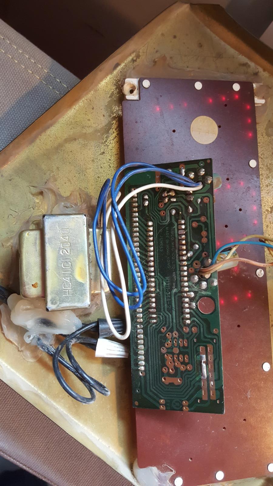
    Got a bit sidetracked by Christmas (Merry Christmas to all!) but finally got a pic done. I agree about the power supply being the problem since when it malfunctions, it acts as if the power went out and came back on.

  15. #9
    Supporting Member metric_taper's Avatar
    Join Date
    Mar 2017
    Location
    Marion, Iowa
    Posts
    585
    Thanks
    227
    Thanked 257 Times in 153 Posts

    metric_taper's Tools
    Well the component side of the board is facing away. Easy to see a transformer connected to the mains, with 3 wires. This has the white wire as a center tap of the secondary, so they are doing a full wave rectification. I can see on the PWB silkscreen where the three wires go through, one is labeled CT for centertap, and this looks to also be the ground reference connection as the circuit trace wraps around the board. I don't see any cold solder joints, but that may be the camera resolution or hidden by munge.
    I would look for a loose connection as the photo shows it's working now. Check out all the solder joints. You could touch the ones up in the power supply area of the board around where those low volt power wires are going through. Can you pull the board back to see the other side better. Look for any damaged capacitor, or lead that is broken. There must be 2 diode at least from the blue wires to a positive connection, I'm guessing they are using a fixed regulator, that would be a 3 terminal part, this would take the rectified voltage from ~8-12VDC down to +5VDC.
    When it flashes, does it loose the time setting? If so, then I'm guessing the main power is the problem, if not, then it might be the supply return wire between the boards.
    Start by inspecting all solder connections on each assembly and carefully look at connections between the assemblies.
    Good luck.

  16. #10
    Supporting Member baja's Avatar
    Join Date
    Dec 2017
    Posts
    249
    Thanks
    7,599
    Thanked 81 Times in 59 Posts

    baja's Tools
    Quote Originally Posted by metric_taper View Post
    Well the component side of the board is facing away. Easy to see a transformer connected to the mains, with 3 wires. This has the white wire as a center tap of the secondary, so they are doing a full wave rectification. I can see on the PWB silkscreen where the three wires go through, one is labeled CT for centertap, and this looks to also be the ground reference connection as the circuit trace wraps around the board. I don't see any cold solder joints, but that may be the camera resolution or hidden by munge.
    I would look for a loose connection as the photo shows it's working now. Check out all the solder joints. You could touch the ones up in the power supply area of the board around where those low volt power wires are going through. Can you pull the board back to see the other side better. Look for any damaged capacitor, or lead that is broken. There must be 2 diode at least from the blue wires to a positive connection, I'm guessing they are using a fixed regulator, that would be a 3 terminal part, this would take the rectified voltage from ~8-12VDC down to +5VDC.
    When it flashes, does it loose the time setting? If so, then I'm guessing the main power is the problem, if not, then it might be the supply return wire between the boards.
    Start by inspecting all solder connections on each assembly and carefully look at connections between the assemblies.
    Good luck.
    Many thanks, Metric Taper. I`ll dink around with it and see what happens.

Thread Information

Users Browsing this Thread

There are currently 1 users browsing this thread. (0 members and 1 guests)

Tags for this Thread

Bookmarks

Posting Permissions

  • You may not post new threads
  • You may not post replies
  • You may not post attachments
  • You may not edit your posts
  •