
 LinkBack URL
 About LinkBacks


belt powered counter wheel you see pictured spins at a different RPM than the belt the wheel will be to cause the cylinder or shaft tube what ever is loaded in the machine to rotate opposite of the direction of the belt due in part to the wheel being made of a substance that will allow friction contact rotation in order for this to be guaranteed the supports under the cylinder are slightly off center which makes the cylinder lean hevy towards the friction wheel. There is also a calculation table that depicts optimum positioning of the work piece which in the case of my grinder design will require the work piece center line to be slightly below the centerline of the belt roller. By skewing the friction wheel axis a few degrees left or right of the belt roller axis this will cause the work piece to travel in the direction of the skew.Originally Posted by metric_taper

Optimally I would drive the friction wheel with a separate drive motor connected to a VFD for rotational speed control.
As the build progresses I may find myself heading in that direction or that may be changed out and added at a later time.
I still have to design the feed on feed off rolling support for this machine as well but that is a simple matter of using a series of inline skate wheels.
Here are some pictures of machines that show some of what I will be doing
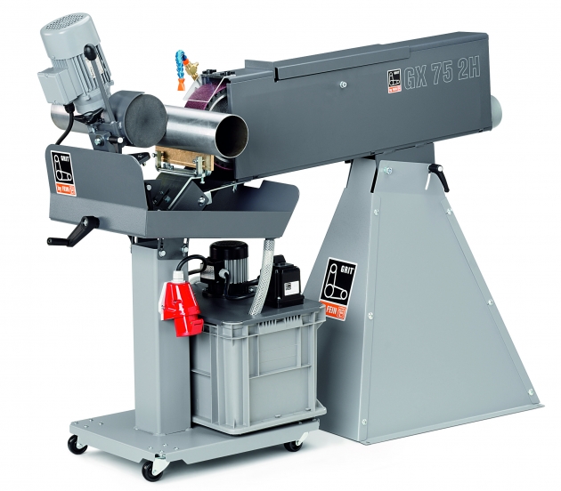
This is a cheap beld grinder with a centerless attachment the complete unit sells for around 3 to 7 grand
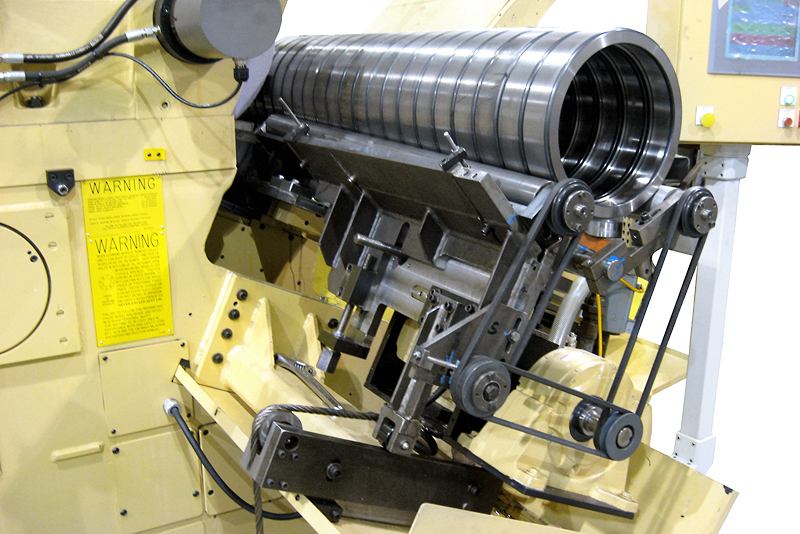
this picture shows the feed on feed off conveyor on a disk wheel centerless grinder quite a bit more elaborate than I will require
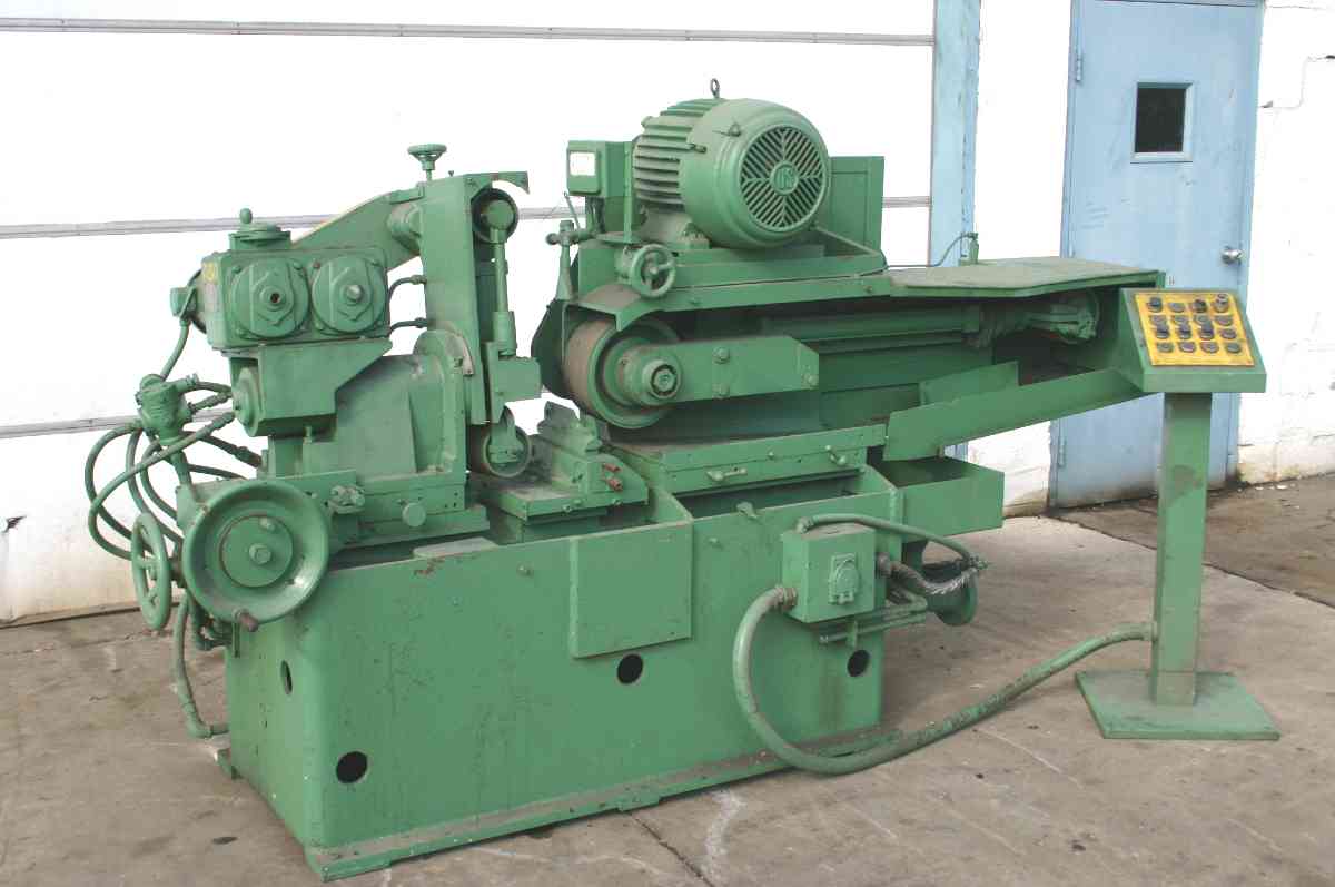
This is a picture of a high end belt type centerless grinder probably 40 years old
So as you see they have been around for a while and I am not doing anything that far out of the box excepting for I am hoping to have minimal cash outlay for a machine which will be far more versatile once I complete it


 Reply With Quote

Bookmarks