
 LinkBack URL
 About LinkBacks

This document focuses on the mechanical system and the electrical system and controls will be discussed in a separate document.
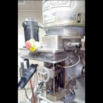
Machine
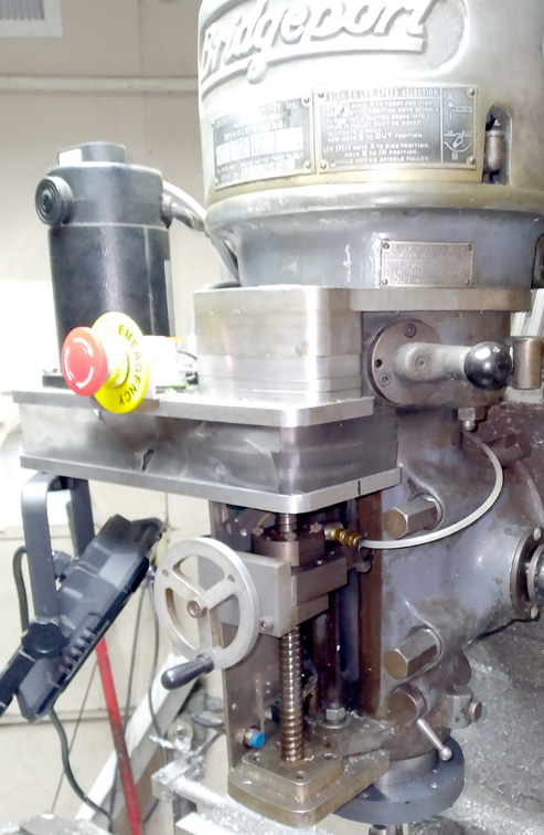
My Bridgeport is a 1966 J-Head model, 9X42, with pulleys to adjust the spindle speed. Since the machine is designed for three phase power, not available in my location, I use a VFD to run the motor. In addition to providing three phase power, the VFD allows speed control by varying the operating frequency. The machine is designed to be operated as a CNC or manual milling machine since some jobs are simpler in manual mode.
Motors & Encoders
A variety of motors are possible from steppers to brushless servo motors. I am not a big fan of stepper motors for two reasons; limited RPM and missing steps. The newer closed loop steppers with encoders should eliminate the missing step problem.
I used brush type DC servo motors, Nema34 size. These were purchased from
automationtechnologiesinc.com
and work very nicely. The model number is KL34-150-90, rated at 600 oz-in peak torque at 38A peak, 90VDC. The continuous torque is 119 oz-in, with a max speed of 6000 RPM.
US Digital encoders are used on the X US Digital encoders are used on the X & Y axis, with a resolution of 2000 counts/rev. The Z-axis encoder will be discussed later.
Leadscrews
The ACME lead screws originally on the Bridgeport are great, but tend to have significant backlash that is undesirable in a CNC system. I converted my machine to ballscrews, which was a bit expensive, but well worth the money when accuracy and repeatability are considered.
CNC Conversion
The first step in my conversion was to create a two-axis CNC system by installing motors on the X and Y axes. This allowed me to fabricate the complex parts needed for the Z-axis by adjusting the Z-axis height manually. A motor drive was fabricated for each of the two axes. The X-Axis drive was attached to the left end of the table by removing the handle and bolting a plate to the end of the table using the existing holes. The handle for the X-axis on the right side of the machine was left in place to allow manual milling. The Y-axis motor drive was mounted to the front of the machine with the motor low enough to clear the knee hardware. The handle for the Y-Axis was also left attached to allow manual operation. Details on physical size of the parts is not shown, and may vary for other machines, especially if different motors are used. Some hobbyists may chose to use metric screws, and bearings used for my conversion may be different from what are required for other machines. Timing belt length may vary depending on pulley spacing.
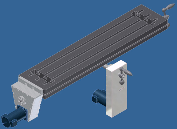
Basic design for X & Y axes
X-Axis details
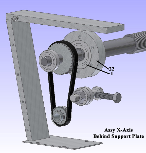
Aluminum plates were cut and drilled to attach all the parts. An XL timing belt drive was used to reduce the speed and increase the torque by a factor of two. The leadscrew moves the table 0.200 inches per revolution, and with the maximum RPM of the motor (6000 RPM), and the 2:1 speed reduction, the resulting maximum X-axis speed is (6000 X 0.2) / 2 = 600 in/min. With the motor encoder having 2000 counts/rev and the linear motion being 0.1 inch per revolution of the motor, this yields 2000 / 0.1 = 20,000 count per inch. The maximum resolution of this axis is 1 / 20,000 = 0.00005 inches or 50 micro-inches.
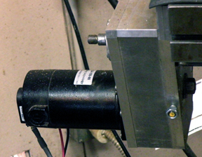
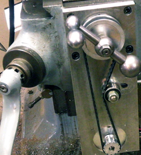
Photo of X Axis
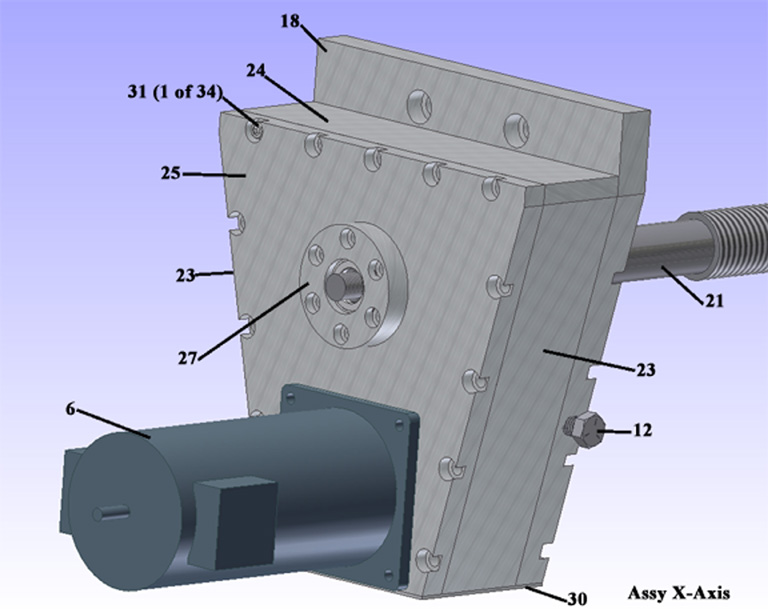
Assy X-Axis
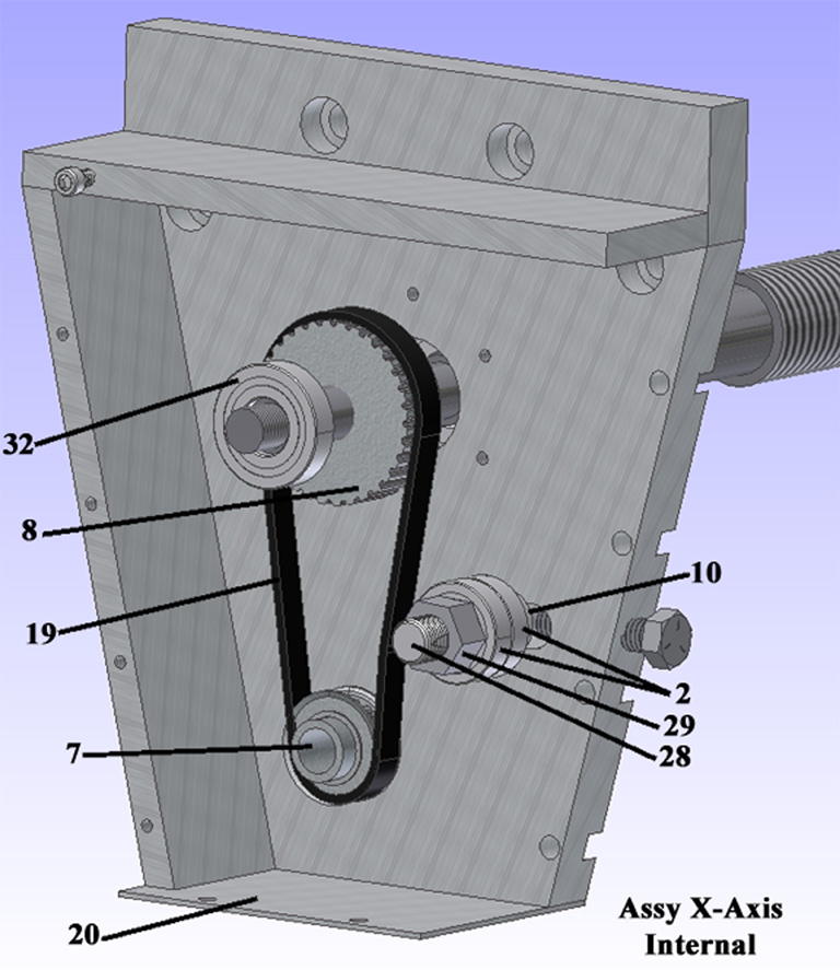
Assy X-Axis Internal
Assy X-Axis behind support plate
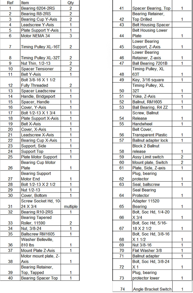
BOM CNC Conversion
Y-Axis
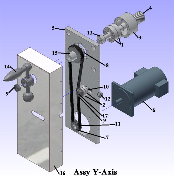
The Y-axis is somewhat simpler than the X-Axis. It uses the same motor and encoders with the same pulleys and resolution as the X-Axis. Installation requires removing the indicator dial and handle for the Y-axis lead screw and installing the assembly. The handle is replaced to allow manual operation. The size of the motor mounting plate may need to be adjusted depending on your choice of motor in order to clear the machine casting below the table. The optional cover will need to be fabricated to fit your design.
Photo of Y-Axis without cover.
Assy Y-Axis
Z-Axis
The Z-axis was designed using a DXF drawing downloaded from the internet years ago, and I do not remember the original contributor.
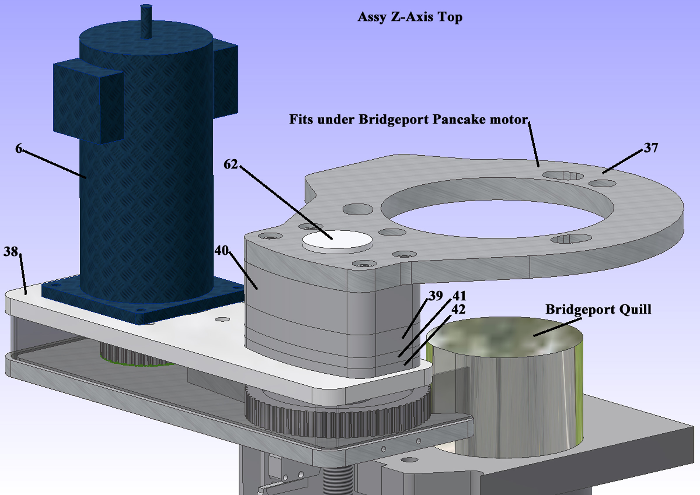
The Bridgeport pancake motor is unbolted and raised, slipping a plate between the motor and the milling machine casting to locate the top of the assembly.
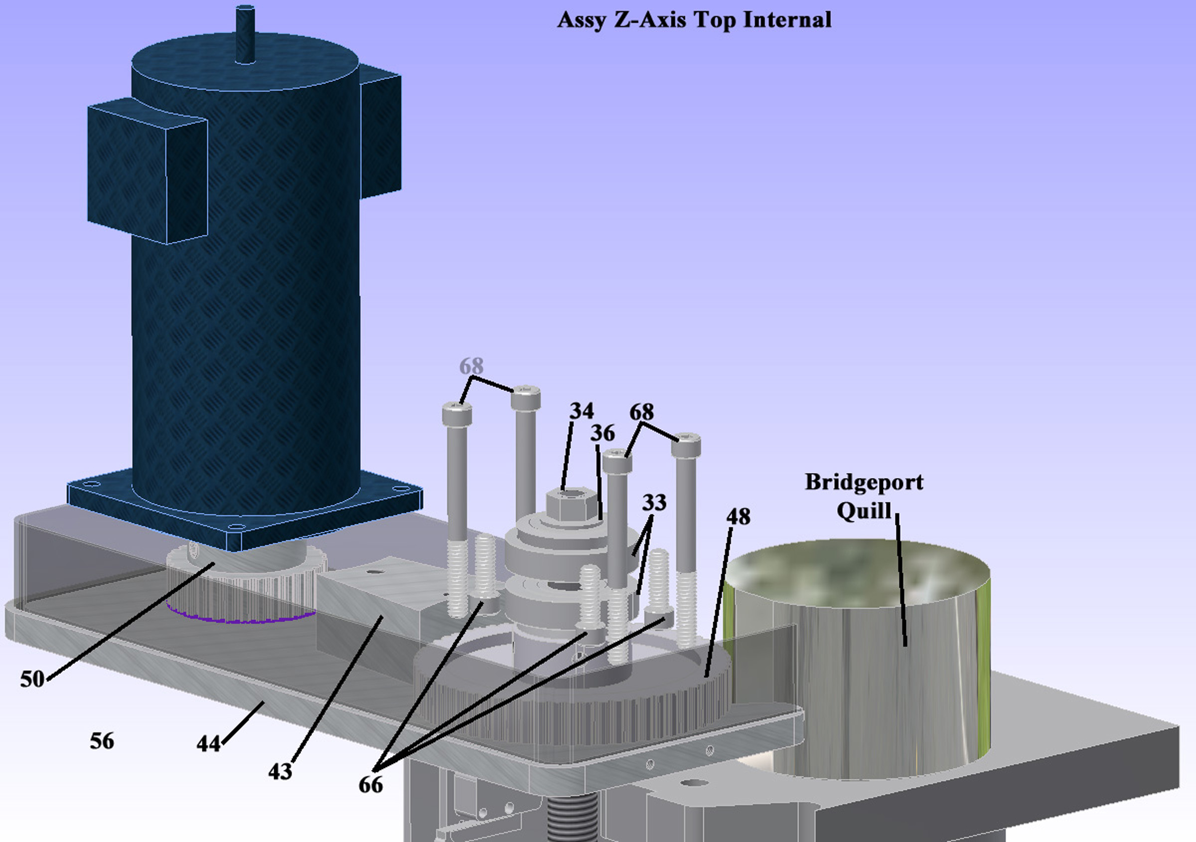
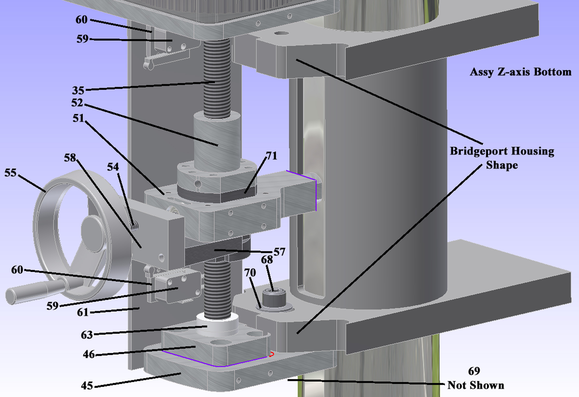
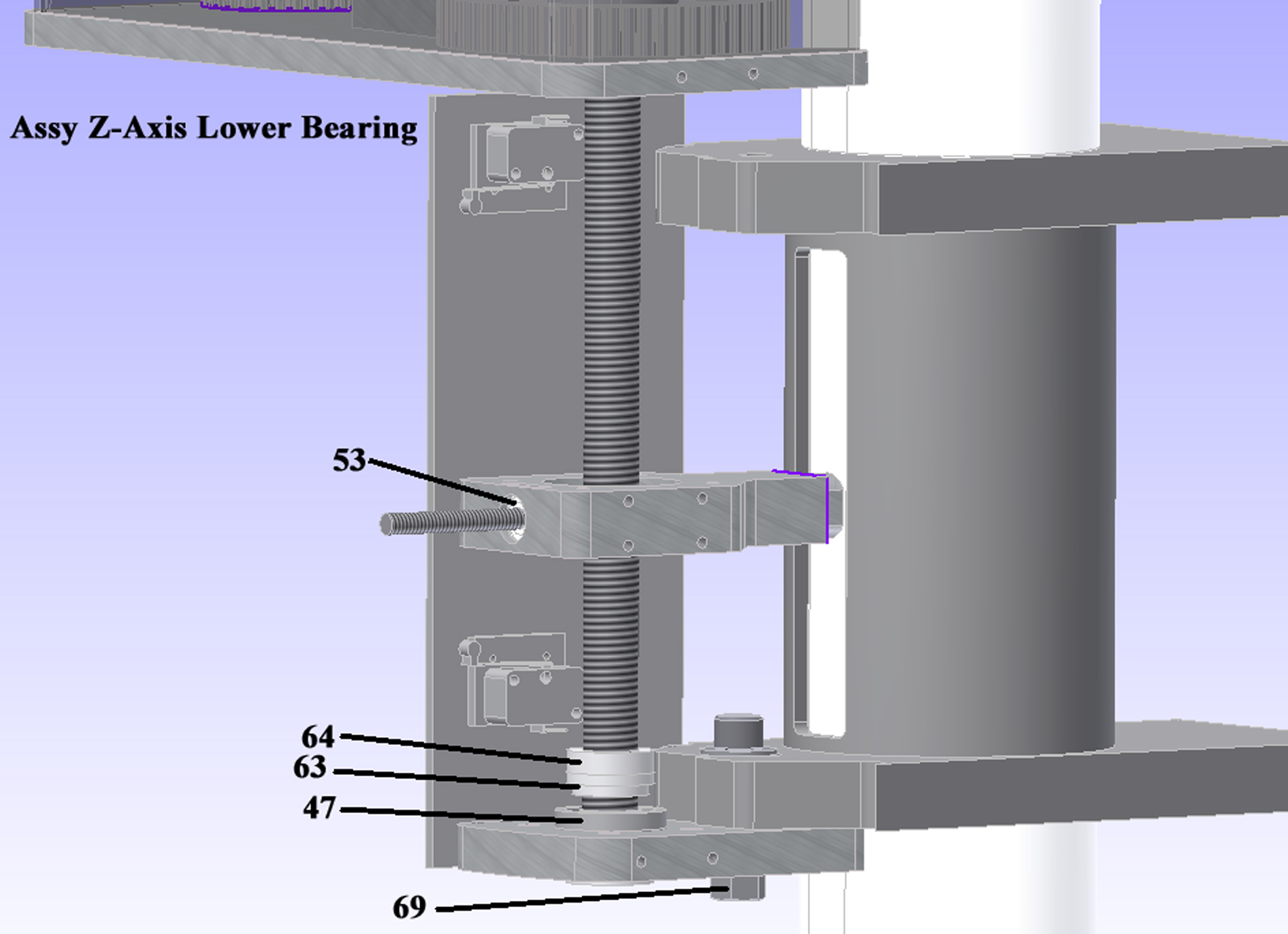
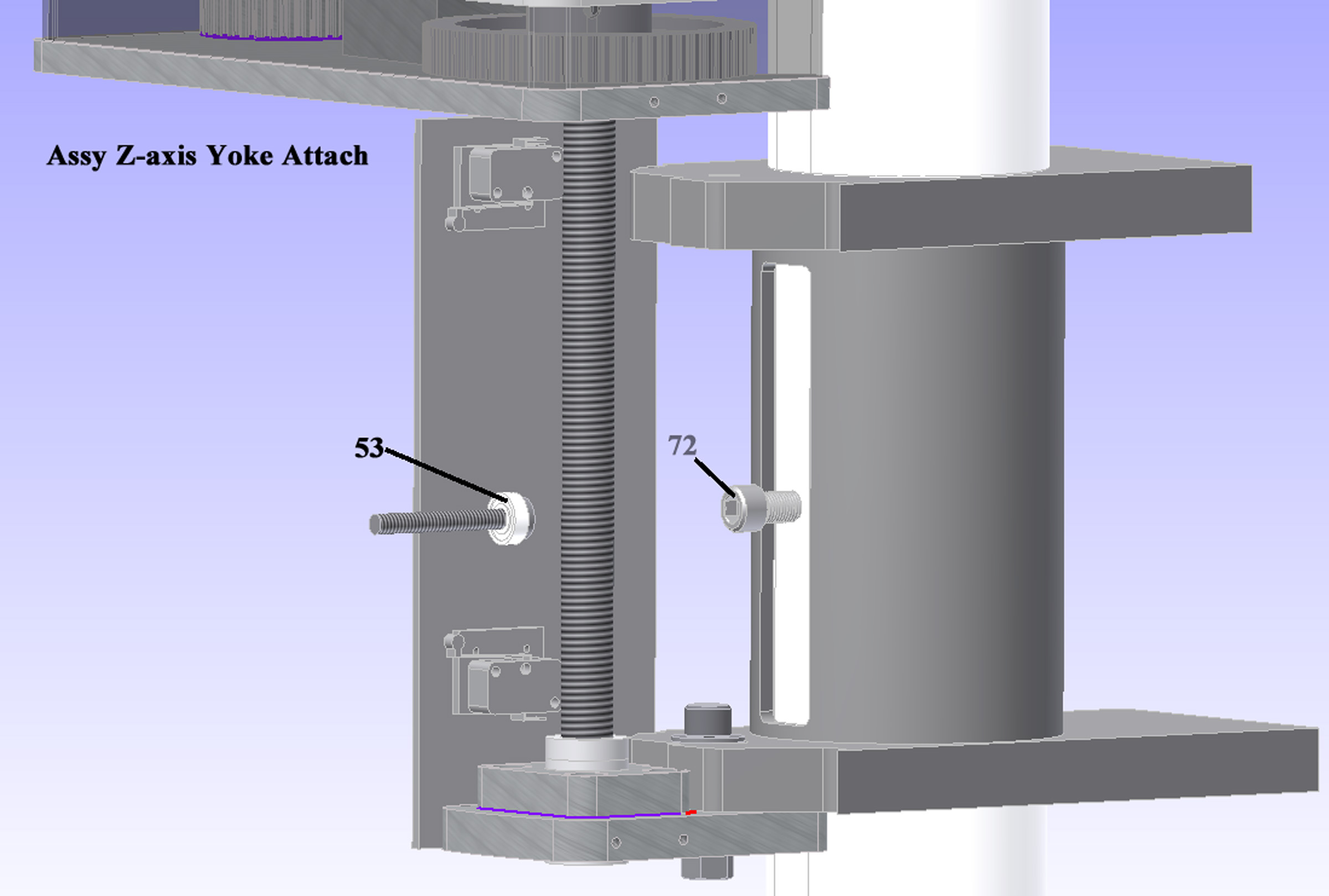
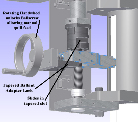
The Z-axis uses a servo motor to drive a ballscrew nut attached to a “Yoke” bolted to the Bridgeport quill. This servo motor uses a CUI programmable capacitive encoder (AMT31-V-553402). Installation of the Z-axis requires removing the quill stop assembly including the micrometer adjusting nut and associated screw used for quill power feed on the original milling machine. The yoke is bolted to the Bridgeport quill using the existing 3/8-24 threaded hole in the quill. A new MR1605 ballscrew and nut is installed in bearings top and bottom. The top bearings (#33) are opposing tapered roller bearings with a Belleville washer (#36) applying vertical thrust to allow the ballscrew to rotate without backlash. The bottom bearing (#47) is bolted to the casting using the hole left by removing the quill stop assembly and keeps the ballscrew aligned vertically. The ballnut (#52) is attached to the yoke with a sliding mechanism (#71,57,58,54) operated by a hand-wheel (#55) that permits disconnecting the power drive for manual quill operation. A tapered Ballnut Adapter Lock (#57) is forced into a mating taper on the ballnut adapter (#71) to lock the mechanism for power feed. The NEMA 34 servo motor has a gear ration of 32:63 which produces very close to 0.100 inches of vertical travel per revolution of the motor using the metric 5mm pitch ball screw. This is not really necessary since Mach 3 can be calibrated for the exact feed required by setting the exact number of counts per inch, and other ratios of XL pulleys could be utilized. The 63 tooth XL pulley utilized was custom fabricated for this project, and is attached to the ball screw with a square key (#49) not shown. Limit switches are used to stop the servo motor before the quill is moved beyond the physical limits. Approximately 4 inches of travel is available.
The entire Z-axis assembly is a quite close fit to the machine, and installation requires some thinking. For example the yoke (#51) must be bolted to the quill with the socket head screw (#72) and tightened before installing the ball screw (#35) through the hole in the yoke.
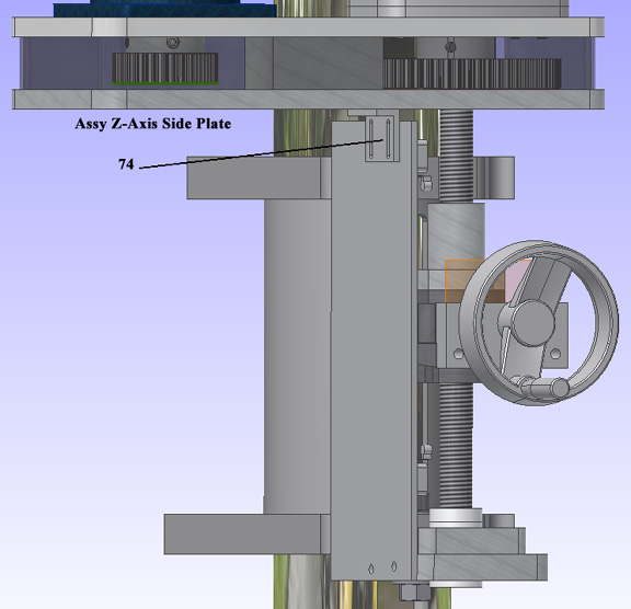
Due to the complex shape of the Z-axis parts it is much easier to fabricate using a CNC machine. If you do not have access to one, I suggest building a two axis CNC and fabricating the parts using it. The limit switches should be attached to the side plate at a point where the mechanism operates them near the limits of travel.
Photo of Z-axis
Assy Z-axis Top
Assy Z-axis Top Internal
Assy Z-axis Bottom
Assy Z-axis Lower Bearing
Assy Z-Axis Yoke Attach
Details of Z-axis ballnut locking mechanism
Z-axis side plate attachment
Drawings
Drawings of the X and Y axis parts are attached in PDF format. For the Z-axis 3D images (SAT) are attached. These may be loaded into a CAD program, or into a CAM program (e.g. BobCadCam) to fabricate the parts.
A future posting will detail the electrical and operating systems.
X-Axis Parts.pdf
X-Axis parts drawing
Y-Axis Parts.pdf
Y-Axis parts drawing
SAT Files
SAT.zip
SAT (1).zip


 Reply With Quote


Bookmarks