
 LinkBack URL
 About LinkBacks


Once more this is a specialised tool for serious petrol heads.
Background
One of the principal ways of improving the power output of IC engines is to increase its ability to breath air. The mechanics of doing this is often called porting. This involves cutting metal away in the ports and sometimes adding material by welding or with epoxy. Some people such as myself are prepared to go further and do a lot of machining and other work to try and get the most favourable port shapes possible within the confines of original head castings.
However, getting the optimum port shape is not straight forward and some trial and error is the norm. Various tools are used to help, a flow bench which measures air flow is the main one, but even with that it is possible to go down the wrong path and the result can be a ruined cylinder head. When I plan to do major modifications I use a different sort of tool which only involves minimal cost if I get it wrong. I make another for testing before attacking the real one. The difference is that the test head is made from cheap plaster.
A specific implementation
I race a Yamaha SRX600 in the US, this started life as a useful street bike with no racing pretensions so the ports were designed without all out performance in mind. It has 4 valves but the two inlets each have separate ports and carbs, unlike the usual 4 valve system of combining the ports into a single port.
Initially I did some quick modifications (away from my flow bench) which produced a useful power increase, but I was sure that more drastic work would produce a much bigger improvement. This would have been a big risk to the head because there would have been no way back to the original if it didn't work well. So I made my plaster tool.
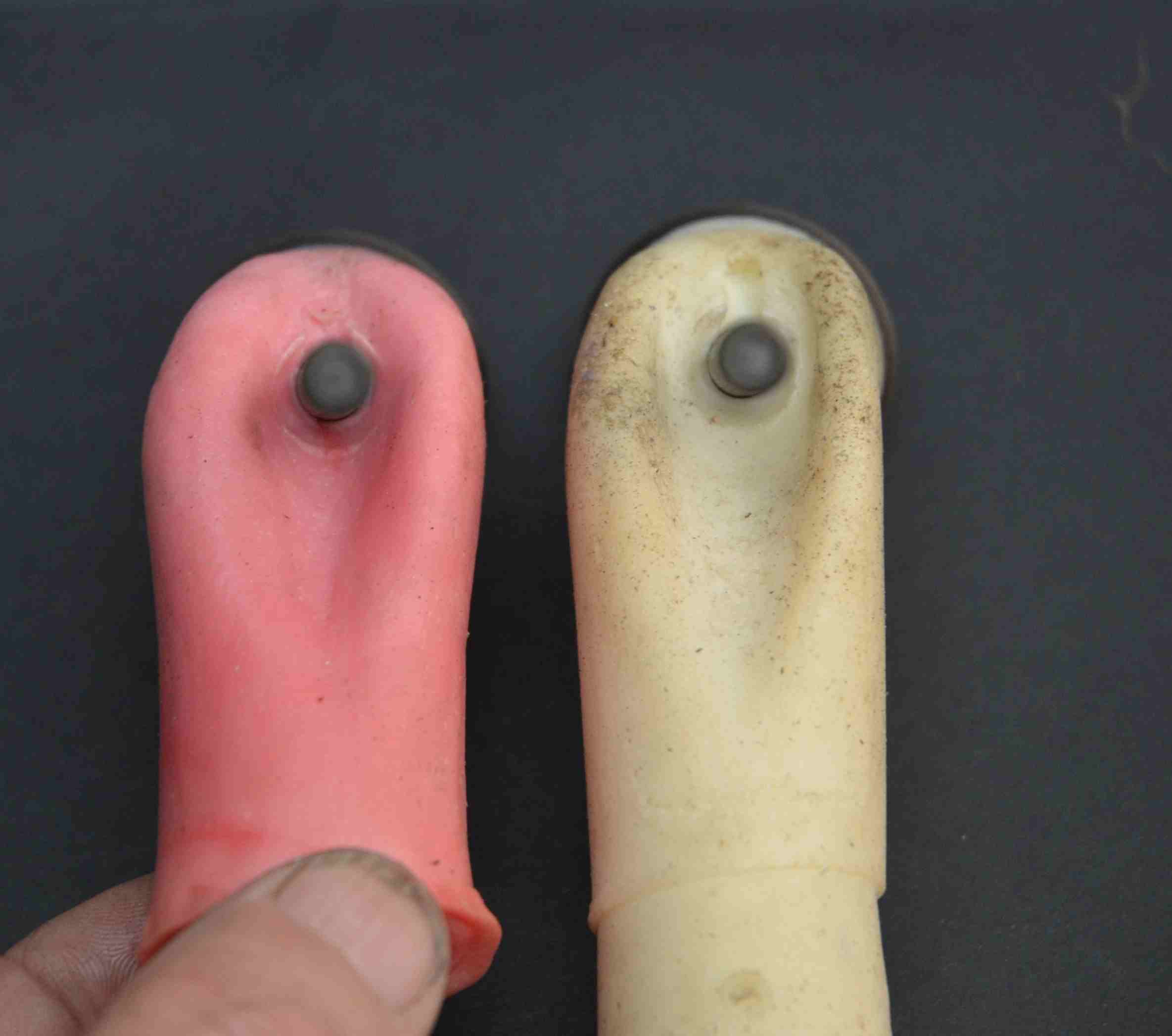
Firstly I had to make a tool to make the plaster tool. This task requires moulding the original ports and combustion chamber of the real head, this is a non-destructive job. There are many moulding compounds that are used for this, some are a two part mix which can only be used once but I use "Vinamold" which can be re-melted and used many times. Resins like polyester and epoxy which set rigid are not suitable for this process because you need a rubbery like material so that you can extract the moulds from the ports.

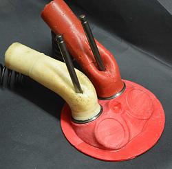
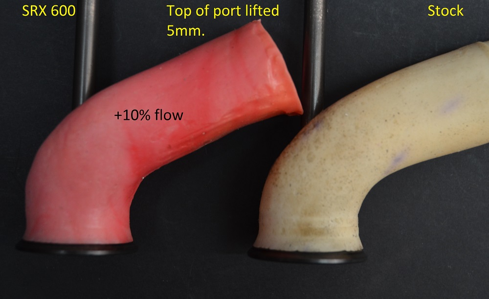
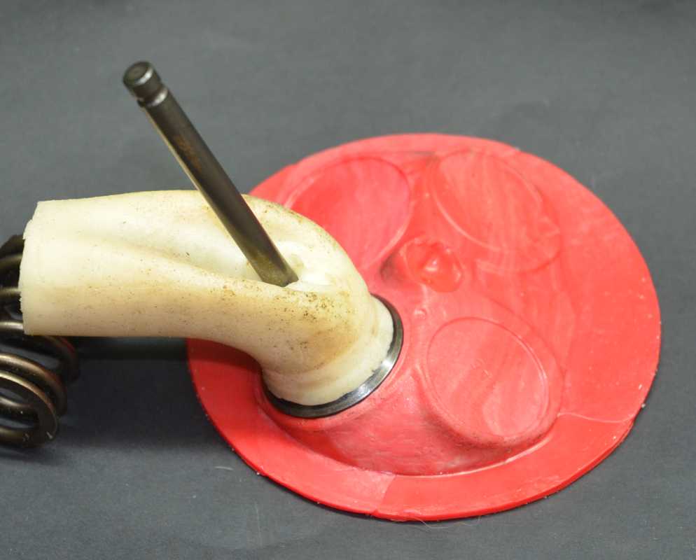
Here we have ports moulds, the pink one is from a port with small modifications which showed a 10% flow improvement over the stock port moulded in white.
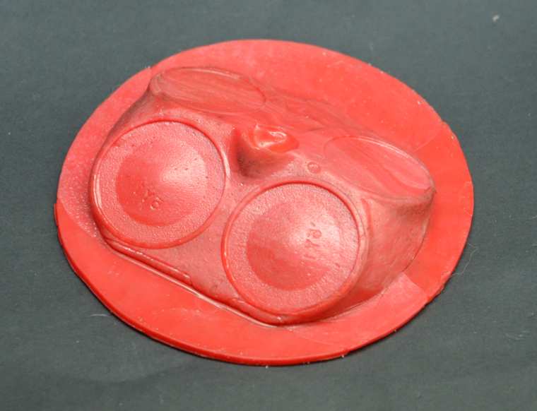
This shows the mould of the combustion chamber.
To produce the plaster head I had to combine the port and chamber moulds as shown here.
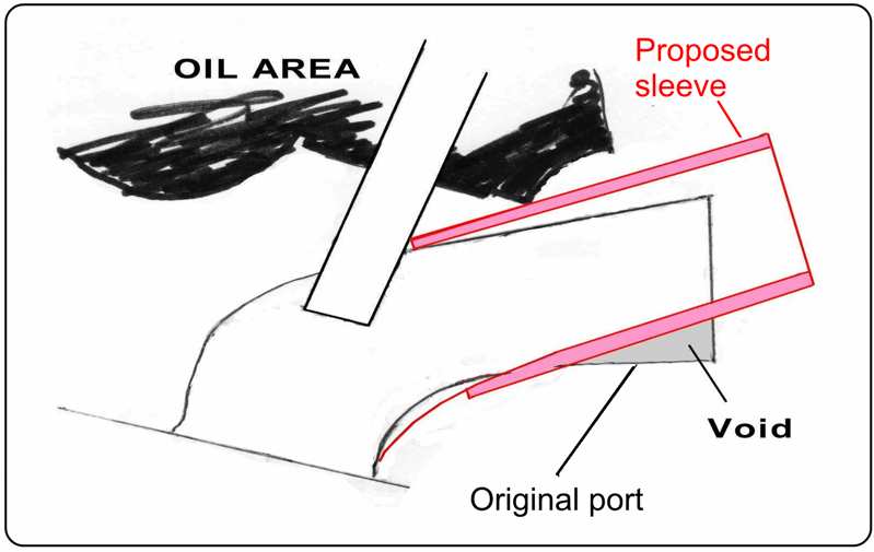
Air flow doesn't like to turn corners and so the best way to get good flow is to aim the port as close as possible to the back side of the valve. This requires raising the port as much as possible. The practical limit to this is breaking through into the lower valve spring seat area, which contains oil. In this case there is not enough metal to raise the port to that height, so I planned to bore out a hole where there was supporting metal and insert a sleeve.
This sketch shows the planned inserted sleeve, It can be seen how much straighter would be the flow path.
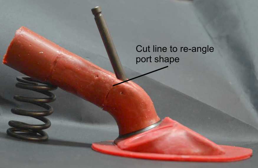
In order to test this with my plaster tool I needed to cast the plaster with the same steep port alignment. To enable that I cut a Vee out of one of the port mouldings and glued it back with a steeper path. The other port mould was left stock which gave me a base for comparison and also a check that the plaster head gave similar flow bench numbers as the real metal head. I call that an "honesty" check.
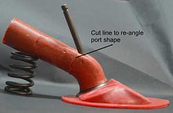
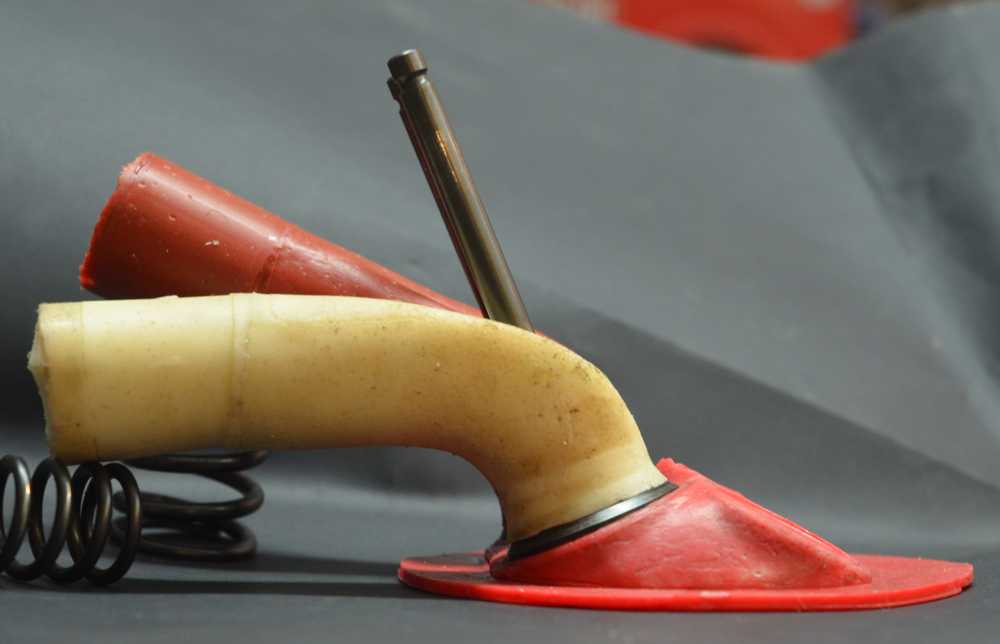
The first pic. shows the steepened port and the second illustrates the large change in port angle between the stock and modified ports.
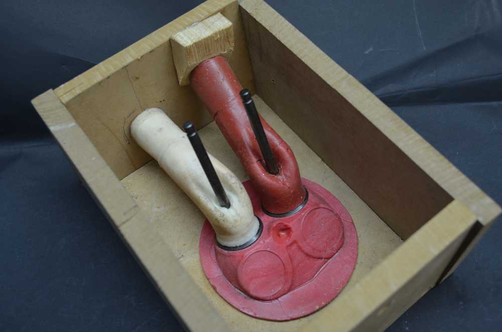
Now was the time to mount these moulds into a box for casting the plaster.

Ready to go.
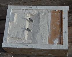
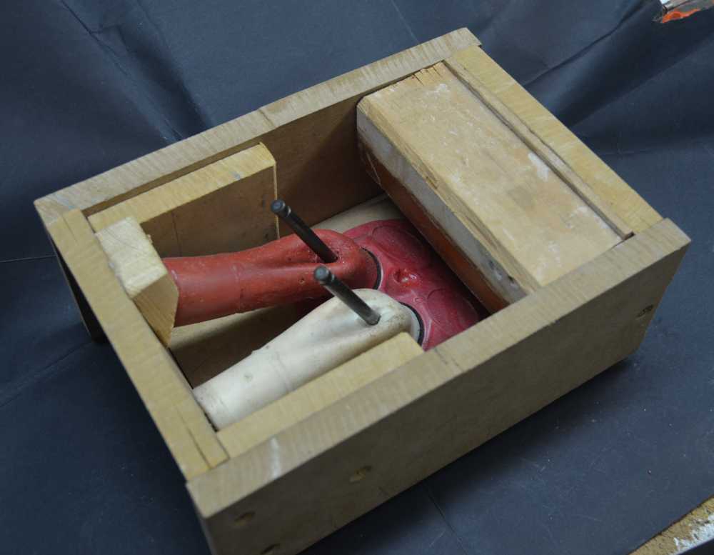
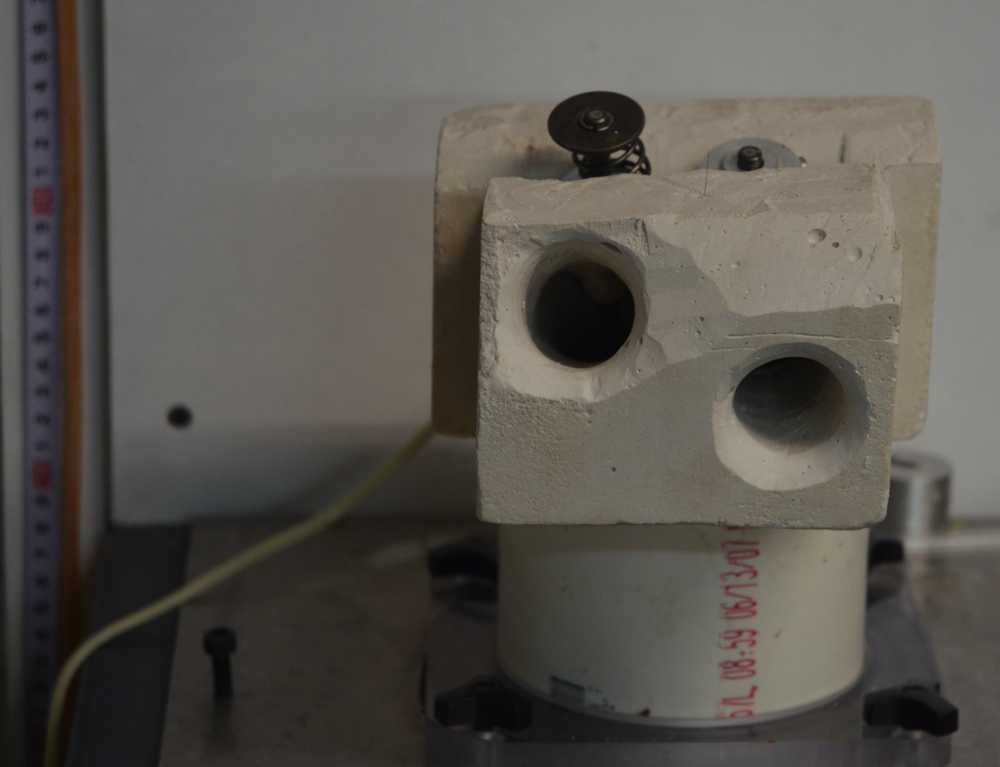
Here is shown the plaster cast, in its box and when removed.
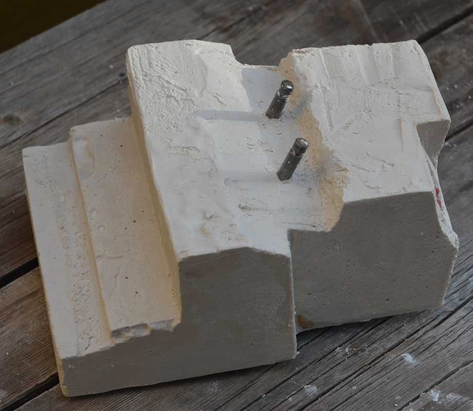
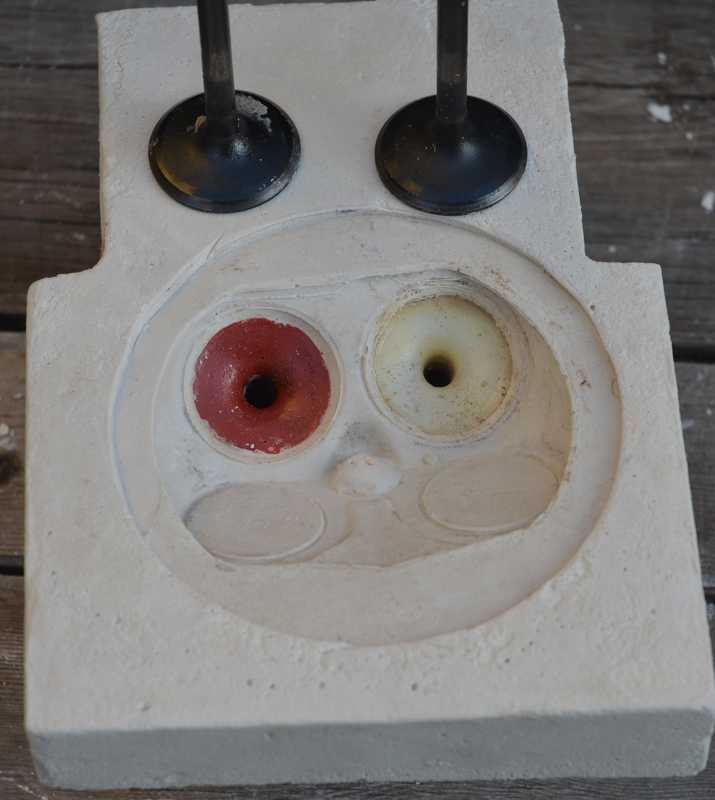
The de-boxed plaster head awaiting the removal of the port moulds.
Note the difference in the air entry height of the raised port compared to the stock one. The entry radius is to smooth the air entry and is common practice when flow testing.
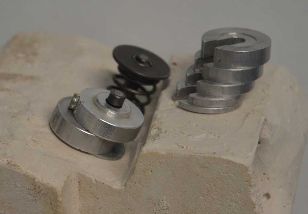
For the flow bench tests, the valve is opened in steps of 0.050" and the flow is measured at each step and processed in my own software. I find the quickest way to do this is to place different width spacers between the base and a collar on the valve stem.
The plaster head was tested and modified and the cycle repeated a few times until I was satisfied with the results. The results were good enough for me to proceed with machining the head.
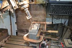
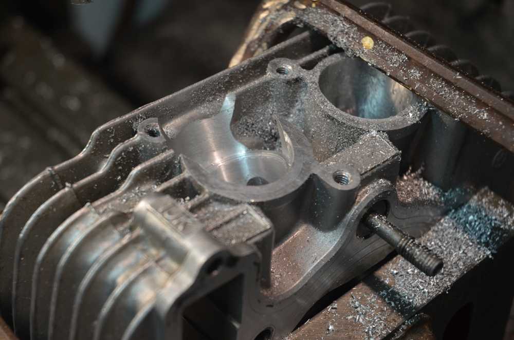
Machining the port to receive the sleeve and the machined head.
To be continued.


 Reply With Quote

Bookmarks