
 LinkBack URL
 About LinkBacks


This is the process I used in my foundry to make and pour a batch of small parts.
The process will vary depending on what is being cast. This uses a multi-piece
pattern to produce 4 parts per cast.
I use greensand which is graded sand mixed in proper proportions with
bentonite clay and water. The is a process in itself. Green sand is much
cleaner, does not smell, and is much less expensive than petro-bond
which is about $3 pound. I have about 40 pounds with about $10 total invested.
While greensand does require some care and maintenance, I find it therapeutic.
I will post making greensand in another thread.
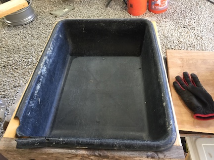
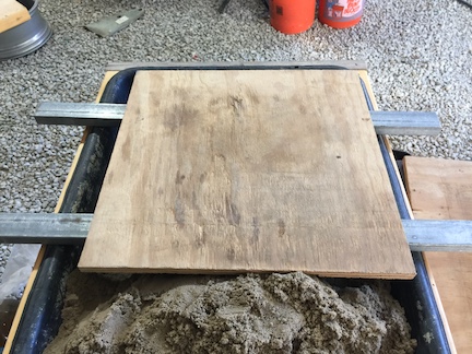
The set up began with a sturdy wood frame to fit a 26-in L x 20-in W x 6.5-in D
Plastic Drywall Mud Pan.
The support is required during the molding process because the plastic pan itself
is not sturdy enough to support the mold while compacting the sand.
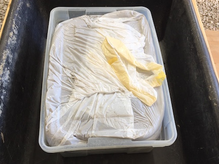
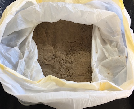
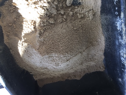
I keep my sand ready to go in a sealed plastic bag. Moisture content is important.
Sand can dry out if not stored properly. It is easier to keep moist than to
re-hydrate if it drys too much

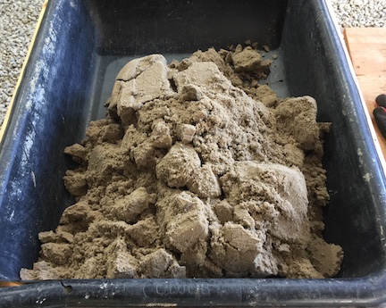
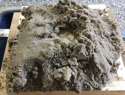
The sand will be lumpy when it is dumped into the pan but will break up easily
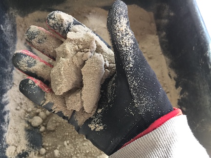
being mixed with your hands. I do use gloves as the sand is abrasive
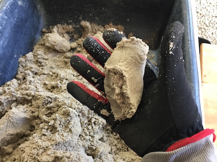
You can tell the sand is right when you squeeze it in your hand. It will form a
firm clump but not stick to your hand or glove. The clump will break easily,
but will not crumble.
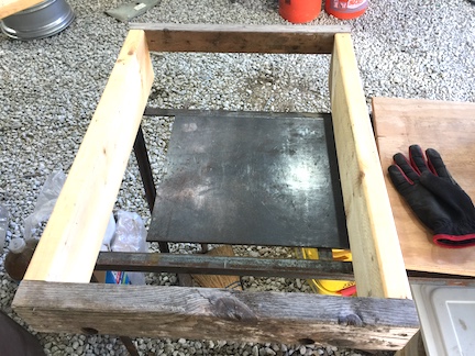
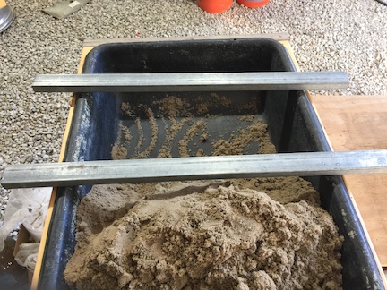
Place two light weight rectangular steel tubes across the sand pan.
I use steel to eliminate a source of splinters in the sand. Wood splinters in contact
with the hot metal will burn leaving makes in the casting.
These bars support a plywood mold board
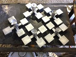
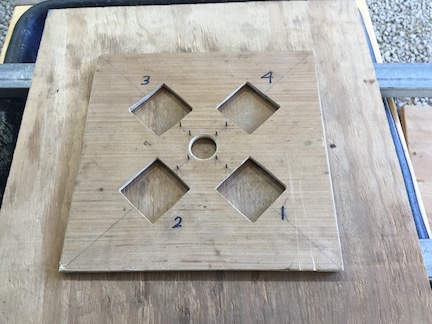
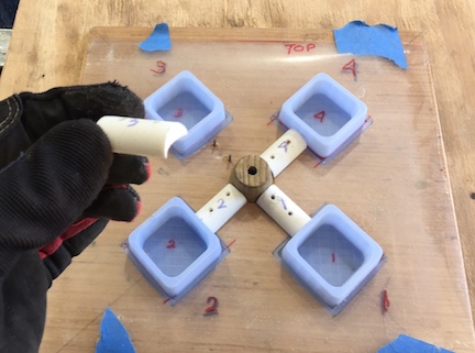
Many times there is just a single pattern involved in casting. For this product
the pattern is made up of 10 parts. They all need to be in the correct position.
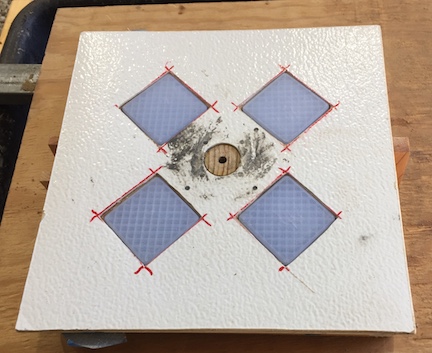
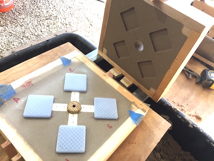
I use board to hold the parts in position. This is the bottom half of the mold
being assembled upside down.
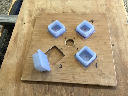
Plastic 3D printed patterns fit into the cut-outs. (Thank you Carl and Steve )
They need to stay in proper alignment while compacting sand around them
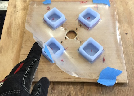
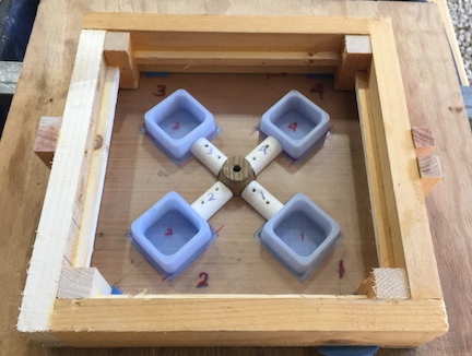
Typically, at this point you would sprinkle a parting compound to keep sand from
sticking to the mold board and the patterns. For this product I am using a plastic sheet.
The plastic parts are slick and need no parting compound. This sheet keeps sand from
getting into the little spaces between the patterns and the spacer board.
Note the 8 small pins in the center to the board.
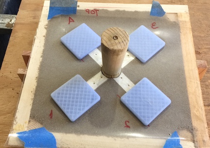
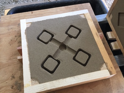
A round wood sprue pattern placed in the center hole. Then semicylinder shaped runners
connect the sprue to each cavity. This shape provides smooth flow into the mold cavity.
Thye are held in position by the small metal pins in the board. The pattern parts are numbered
because the runner patterns were match drilled for the pins, so they are not identical.
A frame, called a drag, is placed around the patterns.
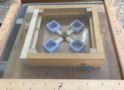
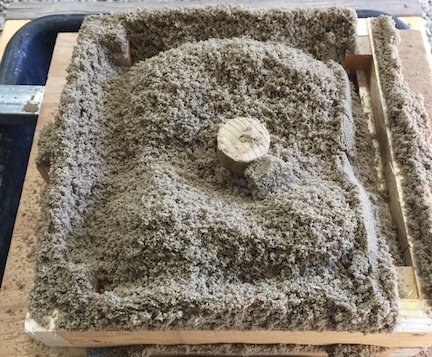
A screen (riddle) is placed over the drag. I used a screen with 1/8 wire spacing.
Technically this actually has 7 squares per inch so it is #7 mesh
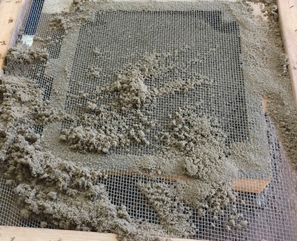
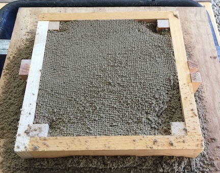
Sand is piled on the screen and worked back and forth to fill the drag.
When it is nearly full remove the screen. The fine sand has covered the pattern parts.
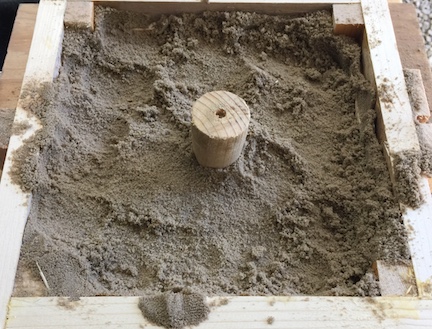
Using your fingers, press the sand firmly into the corners of the frame and around all
of the pattern parts. The sifted sand will be fluffy and compress a lot. If there is not
enough to cover the patterns, sift more over the low spots and compress with fingers.
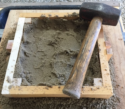
Then carefully but firmly compact the sand with a ram. I find this 3 pound drilling hammer
to be near perfect for compacting the sand. It does not require much force. Just lift and let it fall.
The weight does the work. The handle end for the first layer as shown here
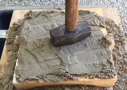
Over fill the drag frame with unsifted sand. Compact it firmly with the large end
of the ram. (head of the hammer)
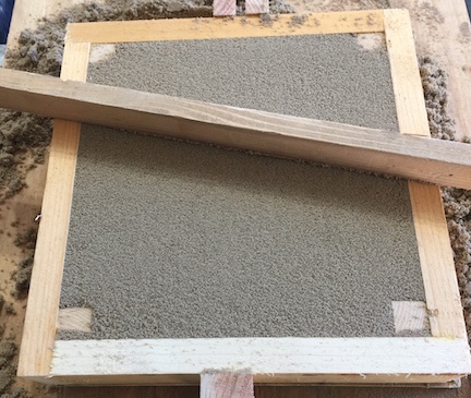
Use a flat metal bar or stick of wood to strike off the excess sand.
This should leave a smooth flat surface on the bottom of the mold frame.
Place another mold board over the drag. Sandwich the mold between the two
boards and turn the mold over. The white is just a piece of self-stick floor tile I
used to make the pattern board thick enough to cover the patterns.
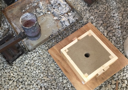
Note the small hole in the sprue base.
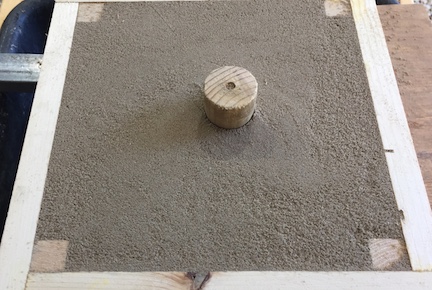
Remove the pattern board while being careful to not lift the patterns. Add the
sprue/riser to the pattern. This cone has a pin that fits into the sprue base.
Place the cope frame over the drag. Sift a layer of sand into the cope
Use your fingers, then the ram to compact the first layer
Add more unsifted hand and ram that into place. Use caution to avoid hitting the sprue pattern
Strike off the cope.
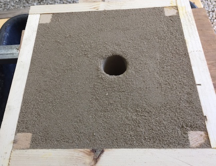
Gently tap the sprue pattern all around the twist and remove, Use your finger to round
the top edge of the opening and blow away any loose sand.
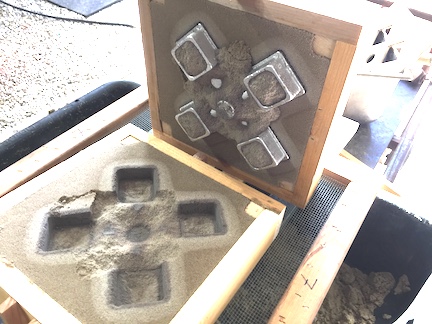
Carefully life the cope. Stand on edge. Examine the mold for defects. At this point, if there
is a major defect in the mold, it is easy to break up and remake it. Rather than make a bad casting.
Gently tap the pattern all around to loosen the sand a little. Then carefully remove each part.
Gently blow loose sand from the cavities. As before, if the mold cavities are defective, you can
remake the mold rather then cast bad parts. Small defects, especially around the parting line
are most common and easily removed after casting.
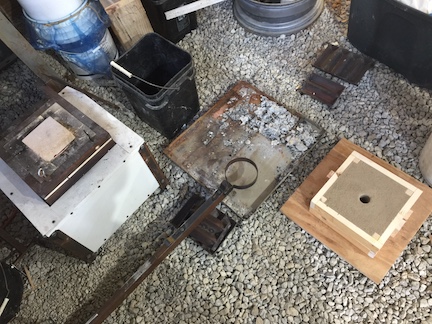
Carefully place the cope back onto the drag and move to the pouring location.
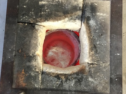
The crucible furnace was started before making the molds. The aluminum is melted
and ready to be skimmed off.
The crucible is set into the holder
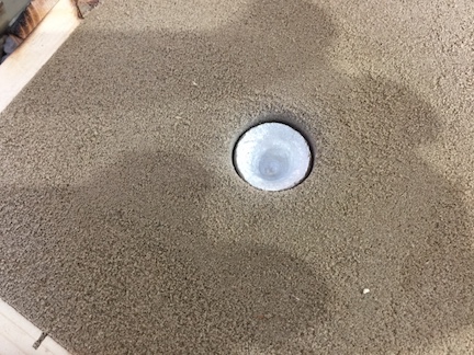
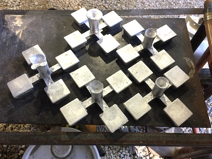
The mold is poured. It happens too fast for me to capture a photo. When pouring stopped,
the aluminum was rounded on top and even with the top of the sand. While, I put the
crucible back into the furnace and got the camera the aluminum shrinks as it cooled and
you could see the dip form as the metal flows down to fill the shrinking cavities.
While one mold is cooling, I make another one. When the second mold is poured,
the first is placed on the screen over the sand box.
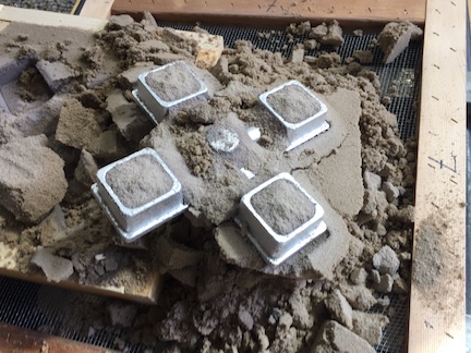
The cope is lifted and set on the bars. You can easily see where the heat has
dried and darkened the sand.
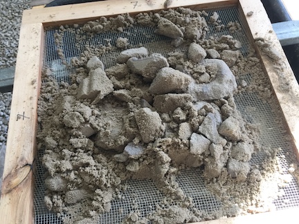
Break the casting out of the mold keeping all of the sand on the screen
While breaking the sand away from the casting rub the hardened clumps of
sand across the screen to break them up. The sand is very warm.
I use gloves to break down all of the sand clumps
At this point the sifted sand warm sand is drying rapidly. Mix it with the remaining sand in the box.
While mixing the sand you will notice that squeezing it will not make a nice firm
clump as before. Loose grains of sand will stick to your hand or glove.
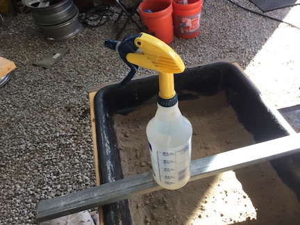
I used a spray bottle to SLIGHTLY moisten the surface on the sand that is spread
evenly in the sand box. Then fully mix the sand to distribute the moisture even
through out the sand. Mist the water over the sand, do not pour the water into
a puddle then try to mix it.
You will know when the sand has the correct moisture content when it makes
that nice clump when you squeeze it in your hand.
I need 40 of these parts. 12 molds will give me 48 in case I scrap any during final machining.


 Reply With Quote


Bookmarks