Free 186 More Best Homemade Tools eBook:  
Get 2,000+ tool plans, full site access, and more.

User Tag List

Results 1 to 9 of 9

Thread: Circuit Board Drill Templates

  1. #1
    Supporting Member rgsparber's Avatar
    Join Date
    Nov 2012
    Location
    Phoenix, AZ
    Posts
    1,278
    Thanks
    735
    Thanked 2,764 Times in 650 Posts

    rgsparber's Tools

    Circuit Board Drill Templates

    Occasionally I etch my own circuit board and then drill it to accommodate through hole components. Components with rigidly positioned pins demand fairly accurate hole placement. This is not so easy when free hand drilling, especially when the drill bit is 0.03 inches in diameter.

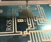
    My solution is to build a series of templates to guide my drilling. They are made from pre-drilled circuit board material so I just cut them out, solder in two alignment pins, and mark the holes.

    If you are interested, please see

    http://rick.sparber.org/SRCBT.pdf

    Your comments are welcome. All of us are smarter than any one of us.

    Thanks,

    Rick

    186 More Best Homemade Tools eBook
    Rick

  2. The Following 8 Users Say Thank You to rgsparber For This Useful Post:

    David Johnson (Jun 30, 2018), logrod (Jun 30, 2018), Paul Jones (Jun 29, 2018), philipUsesWood&Brass (Jul 2, 2018), PJs (Jun 30, 2018), Seedtick (Jun 29, 2018), Toolmaker51 (Apr 3, 2022), Whiteboardwarriors2 (Jun 29, 2018)

  3. #2
    Content Editor
    Supporting Member
    DIYer's Avatar
    Join Date
    Aug 2013
    Posts
    3,056
    Thanks
    772
    Thanked 1,852 Times in 1,653 Posts
    Thanks Rick! We've added your Circuit Board Drilling Template to our Electronics category, as well as to your builder page: Rick's Homemade Tools. Your receipt:


    2000 Tool Plans

  4. The Following User Says Thank You to DIYer For This Useful Post:

    FEM2008 (Aug 7, 2020)

  5. #3

    Join Date
    Jul 2019
    Location
    Ohio, USA
    Posts
    170
    Thanks
    200
    Thanked 96 Times in 49 Posts
    That is a simple and excellent idea. I have etched many a PCB and I know exactly what you mean about drilling holes. it's also quicker than trying to do it on a mill.

  6. #4
    Supporting Member desbromilow's Avatar
    Join Date
    Aug 2012
    Location
    Australia
    Posts
    731
    Thanks
    506
    Thanked 341 Times in 192 Posts

    desbromilow's Tools
    do you etch the "centre punch mark" to aid in drilling? I don't do this enough to claim much knowledge, but I do know they taught us at uni to use pads with a .5mm hole in the centre for the reason of helping to align the drill.

  7. #5

    Join Date
    Jul 2019
    Location
    Ohio, USA
    Posts
    170
    Thanks
    200
    Thanked 96 Times in 49 Posts
    Quote Originally Posted by desbromilow View Post
    do you etch the "centre punch mark" to aid in drilling? I don't do this enough to claim much knowledge, but I do know they taught us at uni to use pads with a .5mm hole in the centre for the reason of helping to align the drill.
    For homemade PCBs, I've always done the layout with an etched hole in the center of the pads. It does indeed help with drill alignment. But, very small drill bits flex and wonder sometimes, especially if I'm not being careful. If there a lot of holes to drill, I tend to get sloppy towards the end. It is good enough for most components though, even IC pins. But as you noted, sometimes more accuracy is needed.

    It's probably been 3 years now, but the last board I did, I, sent to a fab house in China, and for just a few dollars, I got 5-blank pcbs complete with silkscreen. The quality was excellent, and best of all, I did not have to deal with the etching solution. The only complaint was it took a couple of weeks. For $20 more, I could've had the PCBs in in about 4-days, but that was double the cost of the PCBs themselves.

  8. #6
    Supporting Member rgsparber's Avatar
    Join Date
    Nov 2012
    Location
    Phoenix, AZ
    Posts
    1,278
    Thanks
    735
    Thanked 2,764 Times in 650 Posts

    rgsparber's Tools
    Quote Originally Posted by FEM2008 View Post
    That is a simple and excellent idea. I have etched many a PCB and I know exactly what you mean about drilling holes. it's also quicker than trying to do it on a mill.
    Here is the idea generalized:


    Rick
    Rick

  9. #7
    Supporting Member rgsparber's Avatar
    Join Date
    Nov 2012
    Location
    Phoenix, AZ
    Posts
    1,278
    Thanks
    735
    Thanked 2,764 Times in 650 Posts

    rgsparber's Tools
    Quote Originally Posted by desbromilow View Post
    do you etch the "centre punch mark" to aid in drilling? I don't do this enough to claim much knowledge, but I do know they taught us at uni to use pads with a .5mm hole in the centre for the reason of helping to align the drill.
    Yes, I do etch a "centre punch mark" but with the system shown above in the video, I only need them at two points as long as all holes are on 0.1-inch centers.

    Rick
    Rick

  10. #8
    Supporting Member rgsparber's Avatar
    Join Date
    Nov 2012
    Location
    Phoenix, AZ
    Posts
    1,278
    Thanks
    735
    Thanked 2,764 Times in 650 Posts

    rgsparber's Tools
    Quote Originally Posted by FEM2008 View Post
    For homemade PCBs, I've always done the layout with an etched hole in the center of the pads. It does indeed help with drill alignment. But, very small drill bits flex and wonder sometimes, especially if I'm not being careful. If there a lot of holes to drill, I tend to get sloppy towards the end. It is good enough for most components though, even IC pins. But as you noted, sometimes more accuracy is needed.

    It's probably been 3 years now, but the last board I did, I, sent to a fab house in China, and for just a few dollars, I got 5-blank pcbs complete with silkscreen. The quality was excellent, and best of all, I did not have to deal with the etching solution. The only complaint was it took a couple of weeks. For $20 more, I could've had the PCBs in in about 4-days, but that was double the cost of the PCBs themselves.
    I didn't provide any context. These boards are etched by my students so they can understand the process. They also solder in all components and end up with a flight data recorder which is used during the rest of the year.

    Given the technique demonstrated in the video, they can etch a board and drill it in a few hours. During post-mortems of the class, this lab is listed as the most fun. Well, except for one guy that was only interested in software and theory.

    Rick
    Rick

  11. #9
    Supporting Member tonyfoale's Avatar
    Join Date
    Nov 2016
    Location
    Spain
    Posts
    1,564
    Thanks
    688
    Thanked 2,646 Times in 709 Posts

    tonyfoale's Tools
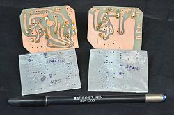
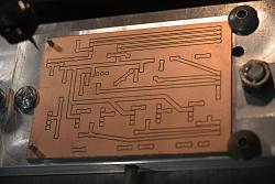
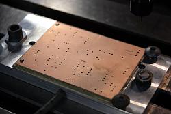
    In the early 1980s I needed to etch a few PCBs and I made simple dedicated drilling guides in aluminium. I would drill the holes first and then use the holes as a guide for hand drawing the traces with a resist pen. Now for simple boards I just use Vero board as a drilling guide but I now do more complex boards by milling.

    Circuit Board Drill Templates-80s_pcbs.jpg Click images for full size

    Circuit Board Drill Templates-donemilling.jpg Circuit Board Drill Templates-perforatingboard..jpg
    Sometimes I still drill first but not always.

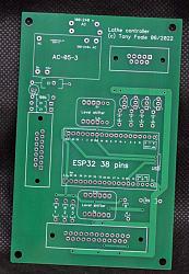
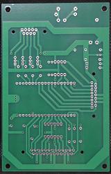
    If I am not in a hurray I now get them made professionally because they are so cheap and on another quality level. Rapid shipping puts the cost too high, which is the reason that I only do this if time is not a factor, but it usually is.

    Circuit Board Drill Templates-realthingfront.jpg Circuit Board Drill Templates-realthingrear.jpg


    186 More Best Homemade Tools eBook

Thread Information

Users Browsing this Thread

There are currently 6 users browsing this thread. (1 members and 5 guests)

  1. flyfr8rs

Tags for this Thread

Bookmarks

Posting Permissions

  • You may not post new threads
  • You may not post replies
  • You may not post attachments
  • You may not edit your posts
  •