
 LinkBack URL
 About LinkBacks

This versatile tool is a great addition to any CNC milling machine, especially a knee mill.
It can be used to cut gears, add splines to shafts, and to engrave on a cylindrical surface. The assembly uses a NEMA32 stepper motor; the type with an encoder is preferred. A two-step timing belt drive system provides increased angular resolution, and tapered roller bearings provide an easily adjustable zero axial endplay. A removable mounting plate can be attached to mount the axis either horizontal or vertical. The compact size easily fits onto the milling machine table. A 4 axis Mach3 or Mach4 controller system can be utilized to drive the fourth axis.
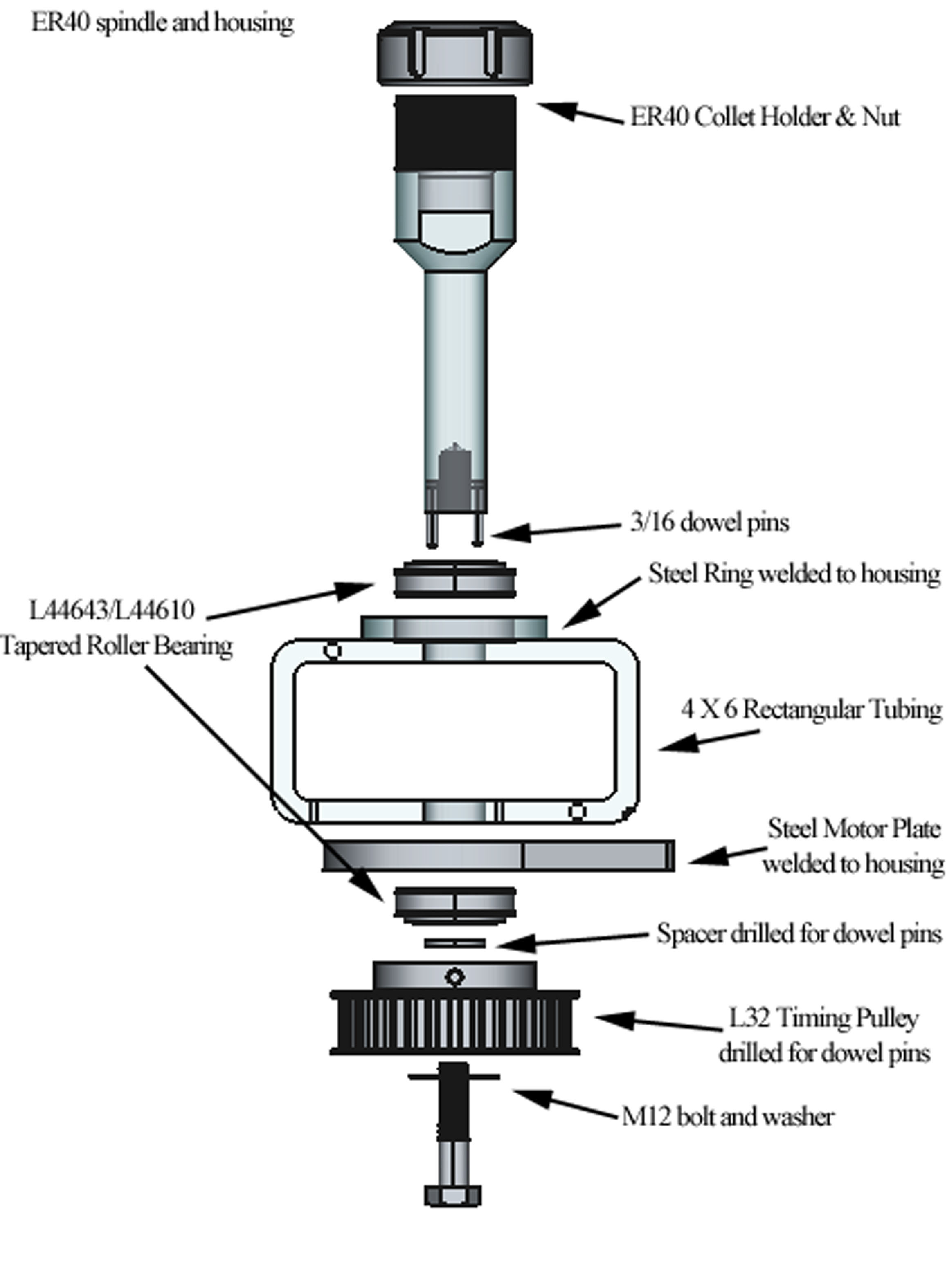
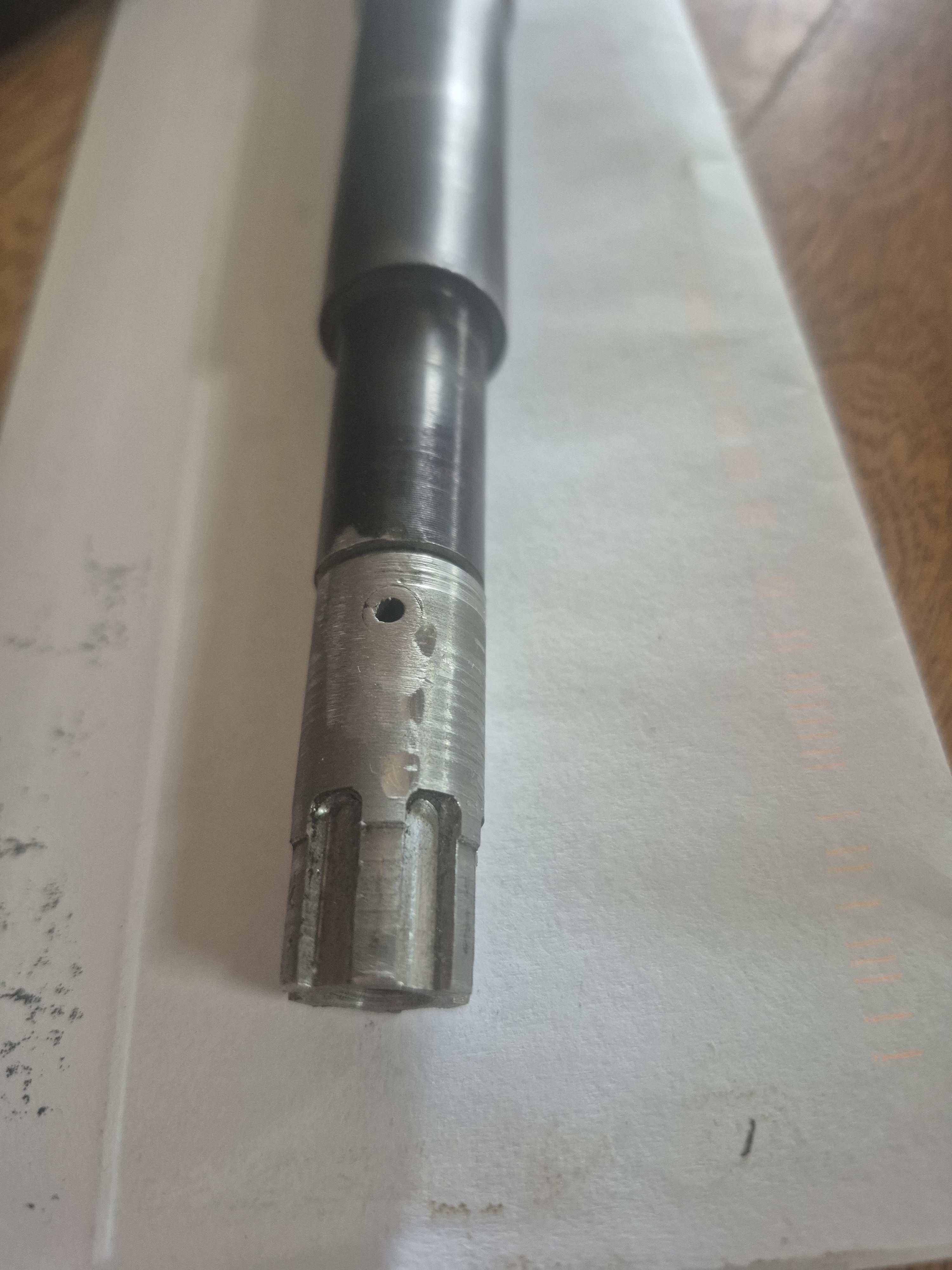
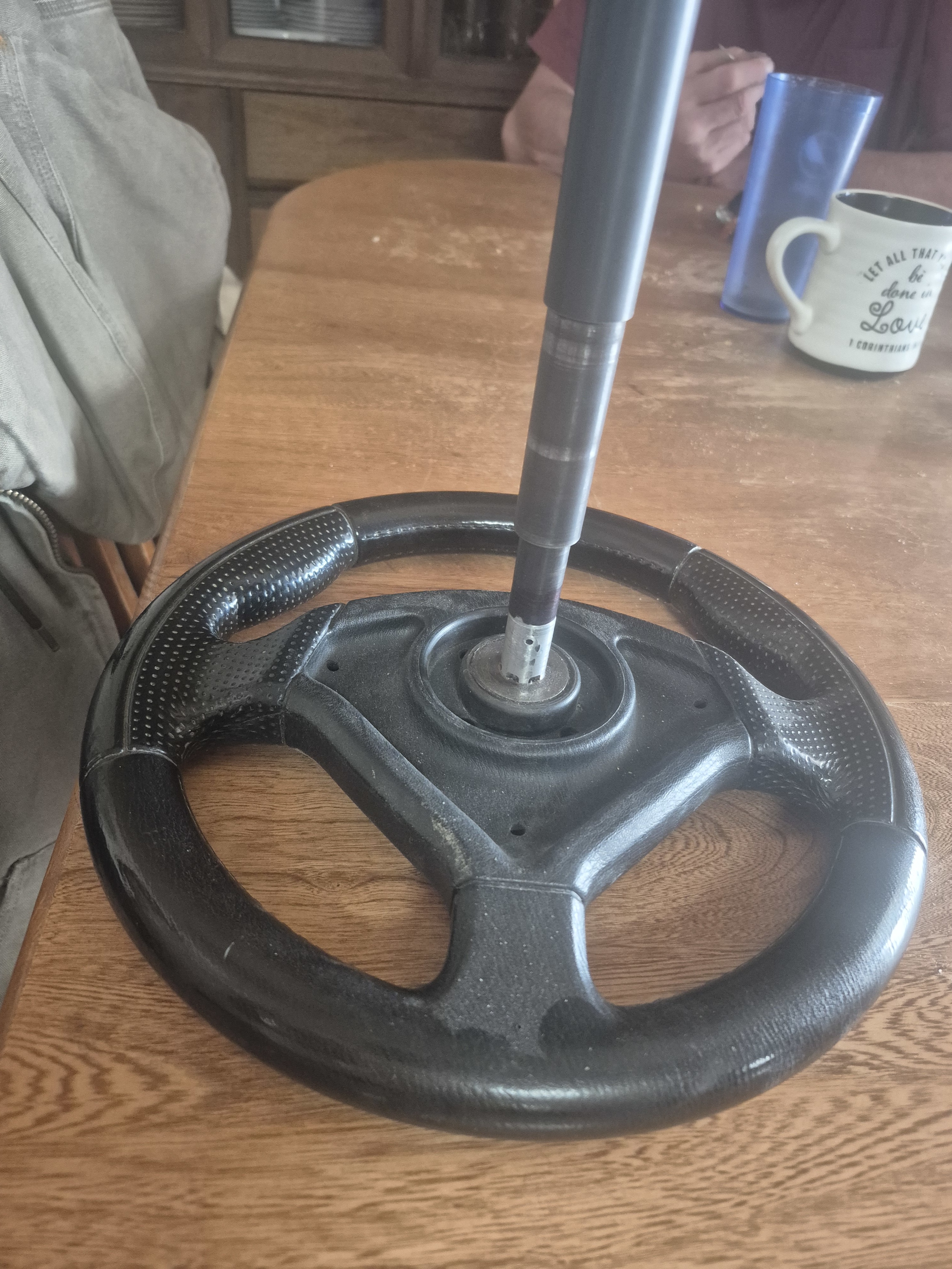
The basis for the tool is an ER40 collet chuck with a 4-inch long 1-inch diameter straight shank. The end of the shank is likely threaded for an M12 bolt. ER40 Collets are available in either inch or metric sizes, and the metric set will hold from 3mm to 26mm diameter round parts. Since the collet sizes overlap, any diameter within this range can be held, either metric or inch size.
The 1-inch diameter shank is well suited to mount tapered roller bearings; L44643/L44610 sometimes called L44643/10 set will fit. These are inexpensive bearings often used on mowers. The OD of the outer race is 1.980.
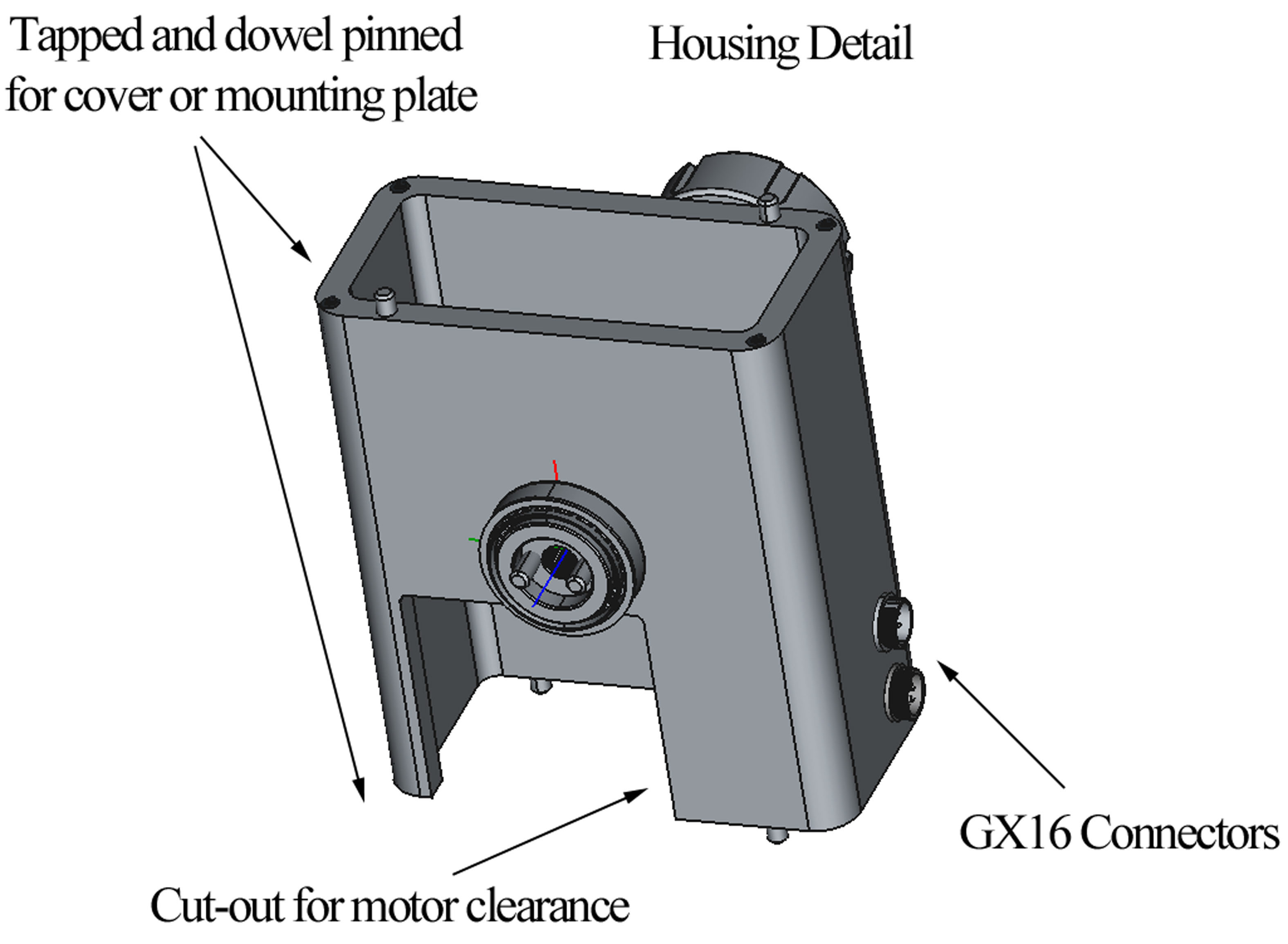
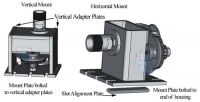
The housing is machined from a rectangular steel tube 4 X 6 inch, with a 0.375 wall thickness, having a cut-out on the side for motor clearance, and both ends drilled, tapped, and dowel pinned to fit the mounting plate or vertical adapter plates.
The housing is mounted to a steel mount plate, with slots to fit the milling machine. This plate is drilled and holes to fit the dowels are added to allow accurate repeat alignment. Two vertical adapter plates can be added, and the mount plate is drilled to attach to these as well, to mount the spindle in a vertical orientation if desired. A rectangular bar to fit the slots in the milling machine table may be added under the mount plate to simplify alignment if desired.
The housing has a cutout on one side for motor clearance. The ends are drilled, tapped, and dowel pinned to fit the mount plate and the vertical adapter plates if used. I selected GX16 aviation connectors for the interface to the motor driver. Since I used a stepper motor/encoder combo, I used a GX16-4 for the motor leads, and a GX16-5 for the encoder. This ensures always getting them plugged in correctly to the controller.
The ring for the bearing is rough machined and welded to the backside of the housing; a motor plate (not shown) is machined and welded to the front side of the housing. After welding, the ring and motor plate are bored to final size for the tapered roller bearings; carefully aligning the housing to ensure it is perpendicular to the bearing bores.
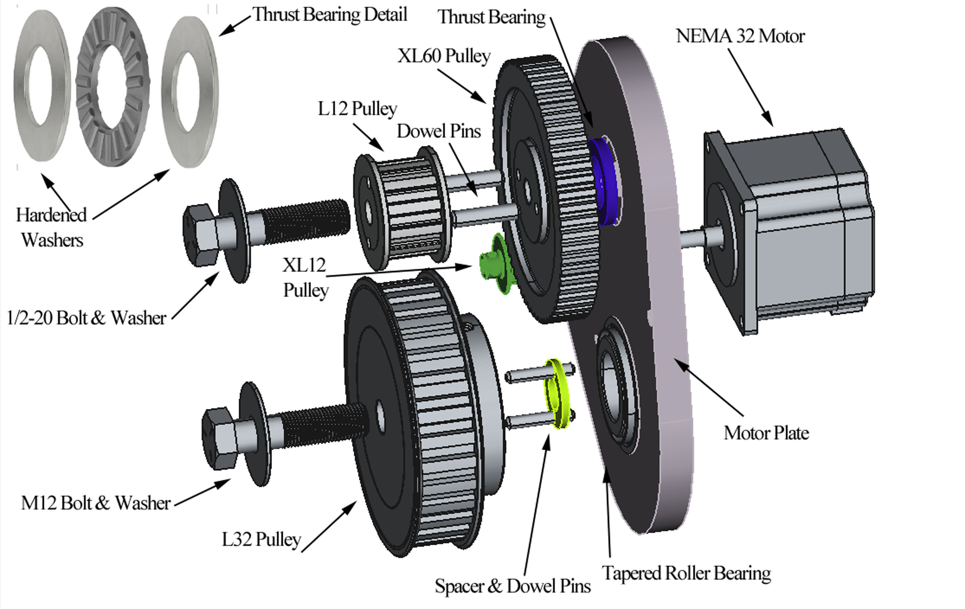
The motor, timing pulleys, and belt tensioners are mounted onto a motor plate after it is welded onto the housing. The timing pulleys I chose were L12 and L32 for the final drive, with XL10 & XL60 for the motor drive. This combination provides a speed reduction of 16 to 1, and increases the stepper motors 200 steps per revolution to 3200 steps per revolution. This calculates to be 0.1 degrees per step. Using micro stepping on the stepper motor driver if desired may increase this further.
The L12 pulley is dowel pinned to the XL60 pulley to provide a zero backlash connection. The XL32 pulley is also dowel pinned to the ER40 collet holder shank for a zero backlash connection. A spacer may be required between the ER40 shank end and the L32 pulley to provide the correct alignment of the two L series pulleys. The XL60 pulley utilizes a flat roller thrust bearing with hardened washers between the pulley and a recess in the motor plate for a low friction fit. The recess depth plus the thickness of the thrust bearing, positions the XL32 pulley for clearance between the motor plate and the L32 pulley. The idler pulley assembly (L12/XL60) is held in place with a ½-20 bolt and washer, threaded into the motor plate. The L32 pulley is attached to the ER40 shank with a metric bolt as required to match the thread in the shank. It may be advisable to use Belleville or wave washers under both bolt heads to apply a spring preload to the tapered roller bearings and the flat roller thrust bearing.
The motor is mounted to the backside of the motor plate, with the XL10 pulley locked to the motor shaft with a setscrew on the shaft flat. Position this pulley axially for alignment with the XL60 pulley.
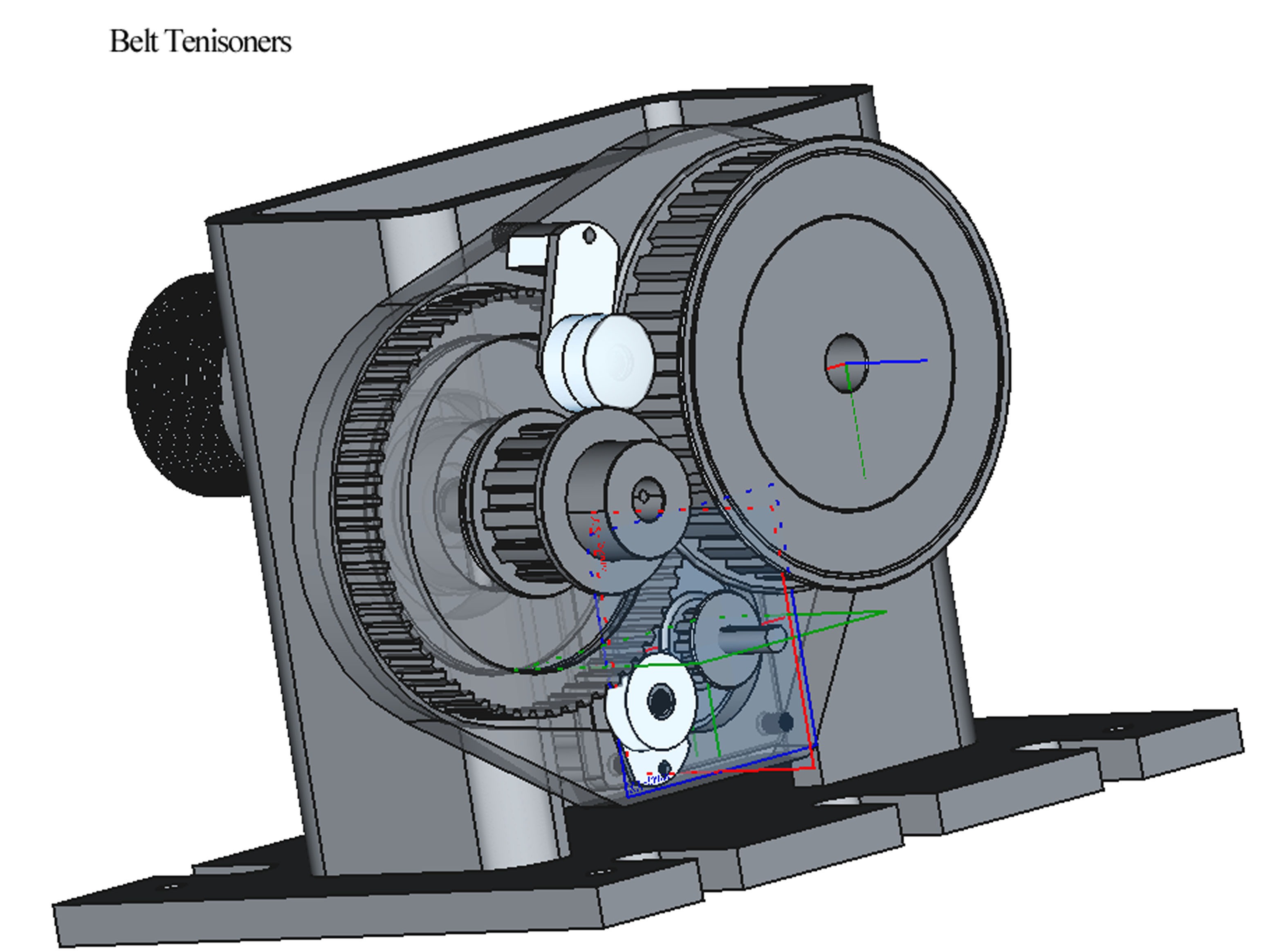
Belt tensioners are added to the motor plate to eliminate any slack in the timing belts and thus eliminate backlash in the speed reducer assembly. I used one or two ball bearings on an eccentric or adjustable arm to apply tension to the belts. A 602-RS bearing is suitable. For timing belts I selected a wider belt for the L series pulleys since it will see more torque than the XL series pulleys. This required using two bearings for the tensioner on that belt.
Mount the fourth axis assembly on the milling machine table. In order to calibrate the unit, I fabricated an arm on a shaft, held in the collet. For one calibration I wanted the A axis to be calibrated in degrees, with 360 degrees of travel being exactly one revolution. I placed a dial indicator on the machine spindle and zeroed it touching the end of the arm. I then rotated the A axis 360 degrees (a 360 f 1000), and measured the vertical position of the end of the arm. I tweaked the motor tuning until one revolution returned the arm to the same vertical position.
To use the fourth axis for engraving on a cylindrical surface, a more useful measurement of the A axis rotation is the circumferential distance traveled by the outside diameter of the part. For example a 1 inch diameter part would travel pi (3/14159) times the diameter, or 3.14159 inches along the surface. You can either adjust the height of your letters, or change the calibration of the motor tuning to travel this distance for one revolution of the motor. For example with a 1-inch diameter, to achieve 0.25-inch letter height, you would need to travel 28.65 degrees.
I needed a M1 48 tooth spur gear to replace a broken gear in my lathe. I wrote a simple G-Code program, installed the M1 gear cutter, and attached the gear blank to the end of an arbor in the collet holder. I used a combination of variables, subroutines, absolute and relative positioning to write the G-Code.
%
O100
#100 = 48 (number of teeth on gear)
#101 = [360 / #100] (degrees per tooth)
#102 = 0 (present angle)
#103 = 0 (new angle)
#104 = 0.089 (depth of cut)
#105 = -0.029666 (incremental Y change)
G20 G40 G49 G54 G80 G90 G91.1
G1 X-1.5 F16 (set feed rate)
G1 X -1.5 Y 0
M98 P1000 L [#100 ] (go to subroutine L times)
M30
O1000 (subroutine)
G1 X-1.5
Y #105 (1/3 depth of cut)
X 0
X-1.5
G91
Y #105
G90
X 0 (2/3 depth of cut)
X -1.5
G91
G1 Y #105
G90
X 0 (full depth of cut)
X-1.5
X 0 (spring pass)
X-1.5 (back to start)
Y 0 (Y back to zero)
G91 (incremental mode)
G0 A #101
G90 (back to absolute mode)
G4 P1 (wait 1 second)
M99 (end of routine)
(END OF PROGRAM)
%


 Reply With Quote


Bookmarks