
 LinkBack URL
 About LinkBacks

The basic idea for the fine feed came from those that where needed for the early Grizzly and Harbor freight Mill drills.
I modified the design to allow for eliminating the backlash in the worm gear. I cast mine from a ZA27 alloy that I mix but it could be cast from aluminum just as well. I turn the ring gear and thread it using a tap as a gear HOB. I have gone to using spiral taps as hobs because there is always a thread in contact with the gear. You don’t need to scribe the first set that way.
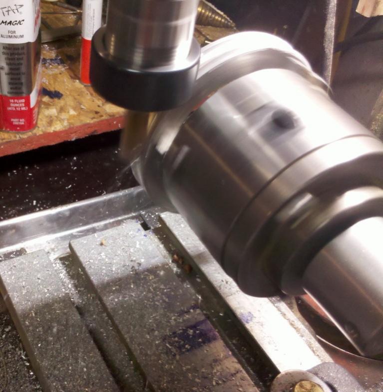
This picture is using a 7/16 mill to cut the cove for the thread in the ring gear. The ring gear is mounted on a 3 jaw lathe chuck that is in turn mounted to a live center and held in the vice. My live center is designed with a ½ x 20 thread for the cones. It allows me to remove the cones and mount chucks etc to the live center for this type of application. My live centers uses a small double row angular contact bearing. By bringing the mill down to the tangent point it cuts and drives the ring gear.
As you can see in this picture this also works with the tap when placing the threads in the ring gear. I turned the tap at about 60 rpm and started with the taper just above the tangent point and feed the tap down until it was turning through the taper and on the full tap. I then run the rpm up to about 550 for a minute or so and allowed it to clean up the threads.
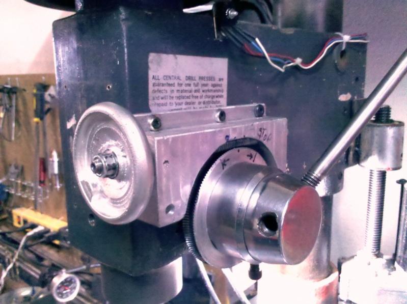
The ring gear is mounted to the drill press ring that was used for a quill stop. This allows the fine feed to be disengaged vary easily when you want to use it for a drill press. The ring gear is bonded to d-press ring with Locktite bearing adhesive.
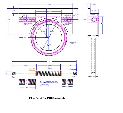
The worm gear is a piece of ½ x13 threaded rod that has been turned down to 5/16 on each end where it goes through the housing. The housing is bored and threaded ½ x 13. The bearing surface inside the housing is made by taking a ¼” brass nipple and threading the outside and cleaning up the inside bore for a bearing. These can also be adjusted to remove the backlash from the worm gear. I use this bearing method most times on items that need a worm/ring gear set. It also acts as a hard brake on ring gear travel. The worm gear on this also extends beyond the housing for the attachment of a z axes drive. I normally just put my vary speed drill on the hand wheel bolts for rough setting and quick moving.

The next set of modifications for this conversion will be to add external springs to the quill. The reason for this is that the spring that is currently lifting the quill is on the pinion which leaves the quill floating. The external springs will force the rack against the pinion and the fine feed will then be in direct down contact with the quill. The weight of the quill and the springs will prevent the end mill form walking in most cases.
The installation of Gibs to the quill will remove the play that is between the head and the quill. At that point you will be able to raise and lower the quill under light cutting loads such as a boring bar, heavy loads like a face mill would still require locking the quill in position.
On this conversion I will use the center Gib screw to lock the quill.

 Reply With Quote

Bookmarks