
 LinkBack URL
 About LinkBacks


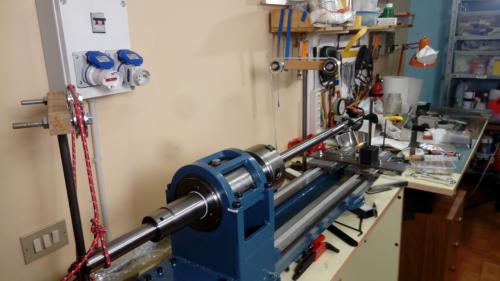
Hi guys, I'm testing some ideas before effectively going into the task of aligning the headstock of my lathe. For this job I'm gonna use a 30mm dia x 1m ground steel bar, as a test bar, that I clamped in the chuck at midway, so that it is balanced on the chuck.
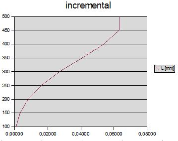
This however would cause some deflection because the weight of the very same bar (as described here: https://en.wikipedia.org/wiki/Deflection_(engineering) see Cantilever Beams section.) To calculate the deflection I used the formula: d = (F * L^3) / (3 E * I) subdividing the bar in segments of 50 mm each and increasing the load at each step, the load given by the weight of the remaining bar overhanging the calculated point. This resulted in a maximum deflection of about 0.06 mm. Using the Uniformity Load Cantilever Beam formula (see the linked Wikipedia page) the resulting maximum deflection is 0.048 mm.
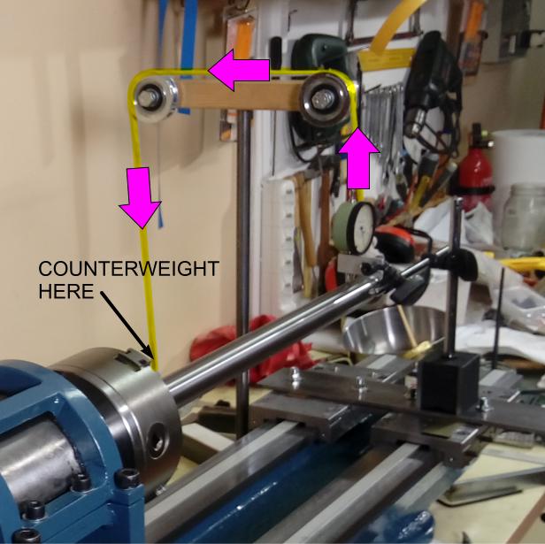
I also thought to experiment a method to compensate the deflection caused by the weight of the overhang bar. I used a couple of pulleys where a string pulls up the bar while on the other side a weight pulls the string down, on both sides of the test bar (see photo).
The counterweight is calculated to be half the total weight of the segment that overhangs from the chuck, since half weight is supported by the chuck.
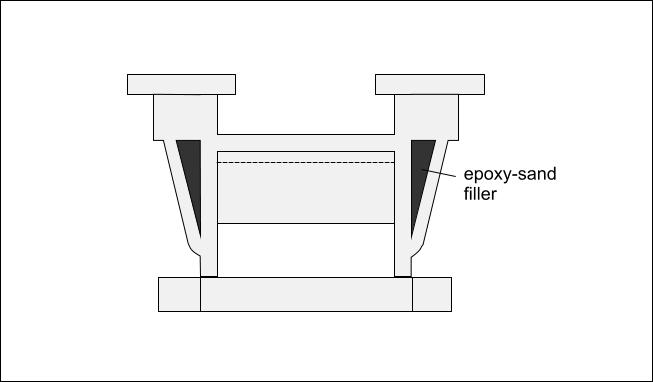
Measurements are not as expected though. With the bar not supported by the counterweight I can't see any deviation. Theoretically the bar should deflect in a bow-shaped way, as in the diagram in figure A. But I measured a perfectly straight bar.With counterweights at each ends I measured a negative deflection of 0.12 mm with a kind of bow-shaped pattern.
Any thought?
Data Summary
Total length of the bar: 1030 mm
Overhang from the chuck: 500 mm (on each side, foreward and backward).
Calculated second moment of inertia: π / 64 * D^4 ; where D is 30 mm (and π is 3.14, in the case the pi symbol won't visualize correctly on your screen): 39760
E modulus: 220000 (C40 steel)
Mass: 0.0000078 * 15mm^2 * 3.14 = 0.0055 Kg/mm (so for 500mm it is 2.76 Kg)
figure A
photo 1
details: how counterweight is attached.
Cheers, Claudio.


 Reply With Quote


Bookmarks