
 LinkBack URL
 About LinkBacks


I have found from time to time that the need for a extended point live center would sure be nice, the longer nose gives you a little extra tool bit clearance, especially for those smaller diameter shafts that require machining on their ends, but to overcome that I would just grind some of the tool bits corner off to clear the point of the live center, some people use carbide inserts with the correct angle to overcome that problem,
I prefer Cobalt H.S.S. bits and I dont liked to grind the corners off !
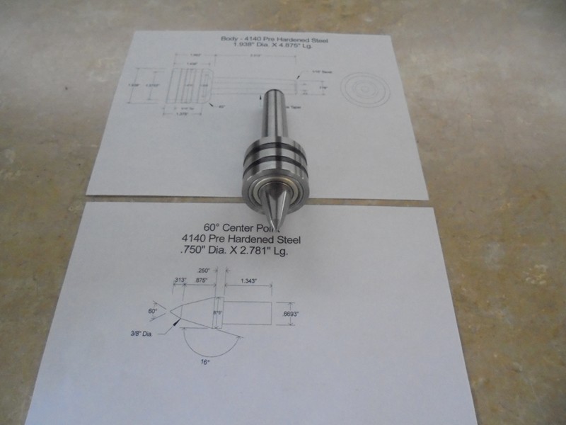
The body has a # 3 Morse Taper Shank; the center rotates in two 5203ZZ double row angular contact bearings,
The body and center point were constructed from 4140 Pre Heat Treated Steel which has a RC hardness of 27-32 which will be quiet sufficient,
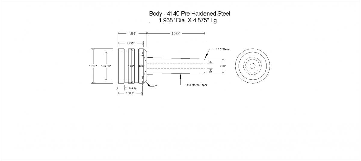
Start by machining the Morse Tapered end on the work piece, set the compound slide to approximately 1 ½ °, then chuck up something with a #3 Morse Taper Shank then indicate in the O.D. where it is running true, check both ends for trueness, mount a dial indicator onto the compound slide and indicate the compound in with the taper shank, chuck up your stock and turn down a straight section 3.313 long and .960 in diameter, using the compound cut the taper onto your work piece, or you may have a taper attachment, the small end of the taper should measure .778 and large end .938, great care should be taken when machining tapers, machining this taper to the measurements I have described and expect it to fit perfectly will not happen, this is just a starting point, when you get the small end turned down to about .790 you need to start checking the fit with something that has a # 3 internal Morse Taper, (this will be your gage), the two tapers should fit perfectly together with no wiggle in the front or back, take several small cuts and adjust the compound as needed to achieve this fit, you should apply high spot bluing to your tapered piece and slip the gage over it and rotate it, this will show the high spots that need some attention, I just use a fat magic marker, your gage should slide all the way up within an 1/8 from the big end of the taper, make sure it doesnt bottom out in the gage, if the gage bottoms out you can always machine some off the small end the work piece, if you machine some off the small end of work piece chances are great you will have to machine the taper further back on the big end as well, leave a couple thousands on the O.D. to polish for a nice smooth finish and that final fit, the key factor here is taking your time.
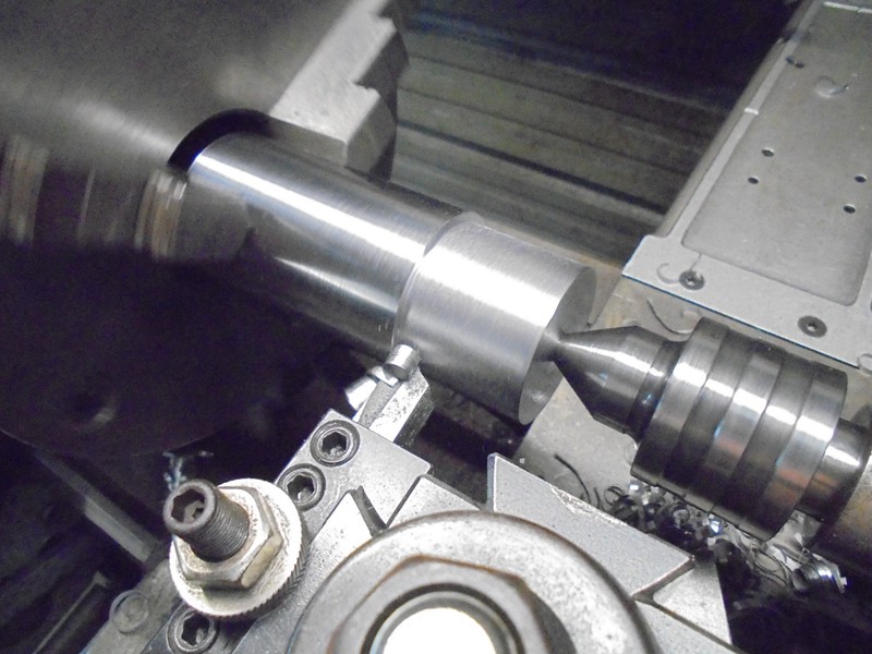
Once the taper was completed I removed the chuck from the lathe and inserted the Morse Taper reducing sleeve that came with my machine into the spindle bore, I inserted the Morse Taper I just machined into the reducing sleeve and gave it a tap with a plastic hammer to seat it firmly, I then proceeded to machine the bearing measurements into the body of the center, See Photos
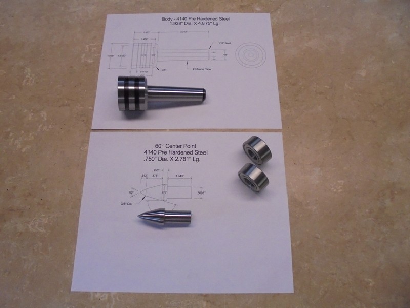
The machining of the center point was done in a one step process, meaning it was machined all at one time without turning the part around insuring 100% concentricity, I started by chucking up a piece of 1 4140 round 7 long leaving 3 ½ protruding past the end of the chuck jaws, after setting the compound to 30° I machined the center point and confirmed the angle with a 60° thread grinding gage, then the 16° secondary angle was machined, I ground up a turning tool similar to a parting tool only it had about a 30°angle on front, this allowed me to plunge into the work piece and feed to the right up to a shoulder to complete the machining of the bearing journal, .003 was left on this diameter for polishing and a press fit for the bearings.
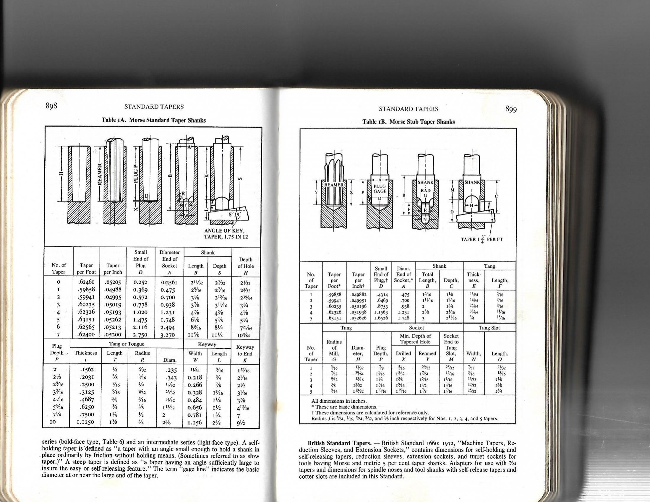
I have supplied multiple photos, drawings, two sheets containing Morse Taper dimensions and this documentation for anyone wishing to make this tool; although this is how I made the tool, it doesnt necessarily mean its the only way.
As always
Thanks for looking
And happy machining
Doug
Roughing in the shank
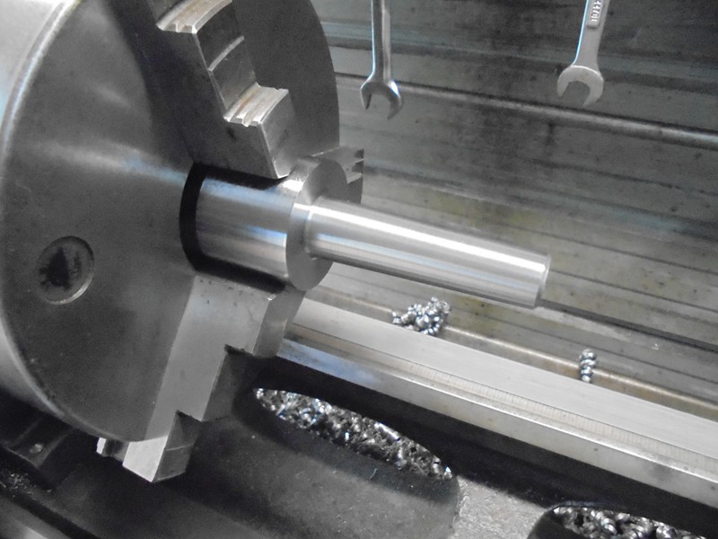
Finished shank
Shank reversed and ready for boring
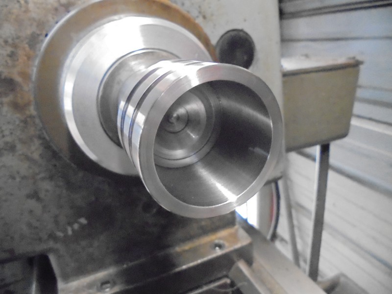
Bored for the bearings
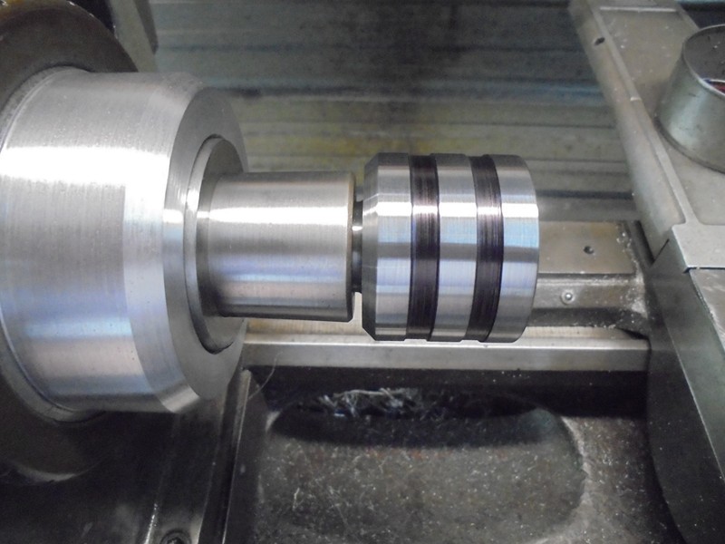
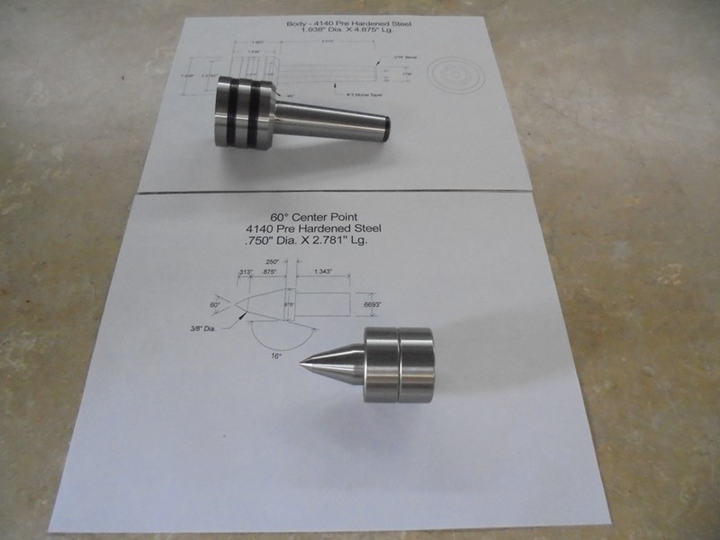
Center made and being parted off
All parts finished
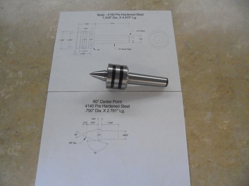
Partially assembled
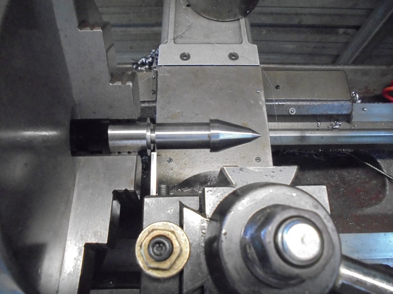
Assembled live center
Front view
Drawing of the body
Drawing of the center
Morse Taper dimensions


 Reply With Quote


Bookmarks