Free 186 More Best Homemade Tools eBook:  
Get 2,000+ tool plans, full site access, and more.

User Tag List

Results 1 to 6 of 6

Thread: Help wanted with sanity check for a 40PA hob cutting tool

  1. #1
    Supporting Member DIYSwede's Avatar
    Join Date
    May 2019
    Location
    Stockholm, Sweden...
    Posts
    634
    Thanks
    415
    Thanked 799 Times in 319 Posts

    DIYSwede's Tools

    Help wanted with sanity check for a 40PA hob cutting tool

    Hi, all!
    I'm (also) obsessed with making a few different (1, .7 & .5) module hobs for cutting involute gears, and have a few question:.
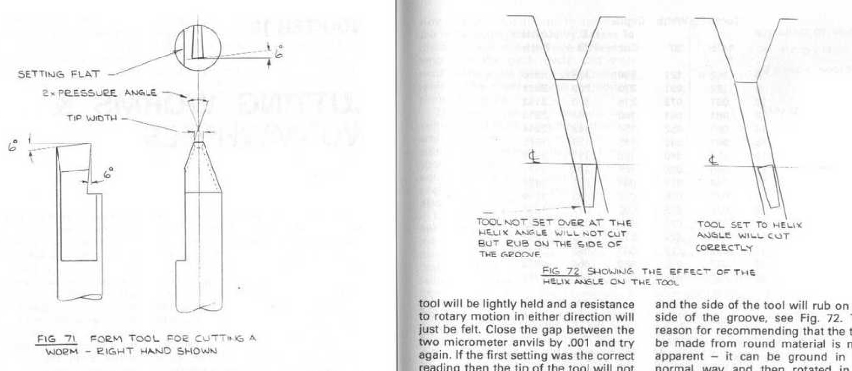
    Pic from Ivan Law's book "Gears and gear cutting":

    Help wanted with sanity check for a 40PA hob cutting tool-40pa-cutting-tool.jpg

    Background:
    To even grind the tool's helix angle and .73 mm front flat tip* of the turning tool as per the right pic above,
    I first need to design the entire hob - Right?

    Mod 1 hob formula for simplicity:
    OD of hob: 25 mm,
    DOC: 2,41 (Addendum 1 mm + Dedendum 1,25 mm & Hob root clearance 0,16 mm = 2,41, correct?),
    so at PI mm worm pitch (as it's Mod 1) and a 22,59 mm average dia of "tread",
    that would give med the helix angle: tan a = 1/22,59, or 2,53 degrees - right?

    If I'm correct above, it would be pretty straightforward to grind the tool by tilting its holder an extra 2,5 degs,
    but then checking its geometry in (say) a Shadowgraph it has to be held at 2,5 degs as in the pic above,
    and not be twisted so as to keep its top edge horizontal, i. e. not kept flat, as in a 40 deg angle gage...

    *A theoretially "pure", sharply pointed 40 deg 1 MOD cutting tool would have a 3,41 mm DOC.
    But this, with its 0,73 mm tip width (thus 1 mm ground off the sharp tip) should then only have a 2,41 DOC,
    to generate a generous enough "non-topping" hob.

    Any ideas/ corrections positively welcome!

    Johan

    186 More Best Homemade Tools eBook
    Last edited by DIYSwede; Jun 18, 2020 at 03:59 AM. Reason: corrected trig & added info

  2. The Following 2 Users Say Thank You to DIYSwede For This Useful Post:

    mr herb (Jun 18, 2020), mwmkravchenko (Jun 18, 2020)

  3. #2
    CanBeDone's Avatar
    Join Date
    Oct 2019
    Posts
    43
    Thanks
    0
    Thanked 38 Times in 18 Posts
    Quote Originally Posted by DIYSwede View Post
    To even grind the tool's helix angle and .73 mm front flat tip* of the turning tool as per the right pic above,
    I first need to design the entire hob - Right?
    Wrong.
    The moment you have chosen the pressure angle and the diameter of your hob, you have set all choosable parameters. The pitch of the hob - if you choose to make a hob with pitch - is then the width of (a multiple of) one tooth at the pitch circle diameter - a derived quantity.
    Quote Originally Posted by DIYSwede View Post
    . . . then checking its geometry in (say) a Shadowgraph it has to be held at 2,5 degs as in the pic above
    Wrong again. Geometrically speaking, the transformation you need to do to get root clearance is called shearing, not rotating. The difference between the two is that in shearing, top and bottom surfaces of your tool remain horizontal; with rotating, they do not. Thus, if you view the tool in your shadowgraph, the cutting surface on which you focus has to be horizontal as well. Rotating the cutter, as your picture shows, is a crutch that can work, but, as your question shows, leads to misunderstanding of what happens during the hobbing process. By recommending this rotation, your book is leading you astray.
    Should you decide to make the cutter / hob without pitch, you need to build your tooling such that both hob and gear rotate in concert. A hob with pitch can be operated by and large without that constraint.
    To understand what I have said here, visualize the hob as a (rotating) broach. If there is no feed forward of the broach during gear cutting (i.e. the hob has no pitch), the gear shape is a direct copy of the cutter shape and not an involute curve. Thus, your milling machine needs to supply that feed forward, and it also needs to couple that to the rotation of the gear blank. But if you build your broach in the form of a screw, feed forward is part of the broach (a hob is another name for a rotating broach), and if you permit your gear blank to rotate freely, the hob will do the move forward action for you - just make sure to pre-cut the blank enough that the hob does not slip.

    2000 Tool Plans

  4. The Following User Says Thank You to CanBeDone For This Useful Post:

    Toolmaker51 (Mar 24, 2022)

  5. #3
    Supporting Member DIYSwede's Avatar
    Join Date
    May 2019
    Location
    Stockholm, Sweden...
    Posts
    634
    Thanks
    415
    Thanked 799 Times in 319 Posts

    DIYSwede's Tools
    Quote Originally Posted by CanBeDone View Post
    Wrong.
    The moment you have chosen the pressure angle and the diameter of your hob, you have set all choosable parameters. The pitch of the hob - if you choose to make a hob with pitch - is then the width of (a multiple of) one tooth at the pitch circle diameter - a derived quantity.
    Thanks for taking your time and correcting me, CanBeDone - I now realize I was unclear in my post,
    and have also revised my assignment since then:
    Namely, to devise a cheap, operative and good enuff gear copying apparatus for (initially)
    three different modules: 0.5, 0.7 & 1M.

    Something like a bigger brother of this "old misdemeanor of mine", with a 1/2" x 12 Whitworth tap as a "hob":
    Help wanted with sanity check for a 40PA hob cutting tool-gear-cutter-frame.jpg

    "The mill" will consist of two (vertically spaced and parallel) horizontal, synchronized axles
    carrying a 25 mm OD bottom hob and a 25 mm top worm "lead screw".

    Same principle, but much flimsier -The "No Frills Meccano Gear Cutter" from a few years back:
    Help wanted with sanity check for a 40PA hob cutting tool-mecc-gear-cutter-assy.jpg

    Perpendicular to this, a horizontally moveable "table" carrying a vertical axle (holding a gear blank fixed at the bottom,
    and the gear to be copied on a free, keyed bushing, constantly meshing with the "lead screw" -
    allowing the liftable axle to move the blank upwards into and thru the hob, while rotating.
    The vertical axle will be slanted according to the hob's and worm's helix angle,
    and DOC radial feed thru the "table's" horizontal feed into the "mill",
    while axial feed is provided by merely lifting the blank's axle.

    Help wanted with sanity check for a 40PA hob cutting tool-blank-holder.jpg

    I got a little confused when planning for grinding the cutting tool, as I assumed slanting the tool
    in accordance with the 2,5 deg helix would significantly alter the tool's 40 deg included angle.
    This was the concern for my previous awkward questions.
    And yes - the 2,5 degree slant would alter the angle 4,38% - which is insignificant -
    so I was barking up the wrong tree.

    Cheers

    Johan
    Last edited by DIYSwede; Jun 19, 2020 at 10:38 AM. Reason: Added hopefully explanatory pics/ fixed line breaks

  6. #4
    CanBeDone's Avatar
    Join Date
    Oct 2019
    Posts
    43
    Thanks
    0
    Thanked 38 Times in 18 Posts
    Instead of answering your implied questions, I will provide you with a link. From that link I have taken this photo
    Name:  IMG_20150726_164328.jpg
Views: 268
Size:  8.8 KB
    which shows a simple way to cut gears using a vertical mill. If you follow the link provided by AI8236, you'll end up on a web site that very much has written down what I think on how to design a gear cutter - VERY different from your ideas. If you add to this that you can buy finished gear hobs for under 50 US$ from e.g. aliexpress.com, that is the way I would tackle gear cutting.

  7. The Following User Says Thank You to CanBeDone For This Useful Post:

    Toolmaker51 (Mar 24, 2022)

  8. #5
    Supporting Member DIYSwede's Avatar
    Join Date
    May 2019
    Location
    Stockholm, Sweden...
    Posts
    634
    Thanks
    415
    Thanked 799 Times in 319 Posts

    DIYSwede's Tools
    Thanks again for your input and links, CanBeDone.

    Realizing that I might be perceived as being polemic and/ or "resistant to counseling",
    this is neither my intention, as I try to consider facts and opinions of others on the fly,
    and relate these to the capabilities, conditions and limitations under which I strive,
    nor is it an expression of any self-pity regarding my lack of a "proper workshop" :


    I do agree with you that a "rack-cutting mill" as per Al8236, Helichron and several others is a simpler way than my suggested prototype.
    As I neither possess a mill nor a dividing head, and absolutely not the patience/ time needed for cutting a gear through stepped indexing:
    To get a decent tooth profile, you'll need at least 4 cuts/ tooth - that would mean >216 indexed steps/ cuts for the pictured 54t gear above.
    Link: Gear cutting with a rack form multi-tooth cutter

    The only advantage I see of a mill tool of this type compared to standard gear cutters, is that you don't need the 8 cutter set/ module or DP.
    OTOH, a cutter would only need 1 index and cut/ tooth whereas the rack mill needs several to get a decent tooth profile.
    Of my self-imposed design criterias, the "operative" wouldn't thus be met (I forgot "fast" as also one of my criterias)

    My quick & dirty prototype (absolutely NOT my invention) having a single helix hob with at least 6 cutting edges/ turn and a "lead screw",
    will achieve both a good enough tooth profile for ANY (20+) tooth gear count gear of the given module/ PA,
    as well as a real fast synchronized indexing of the blank - getting a "plastique" gear duplicated to brass, steel or CI within minutes.

    Another happenstance consequence in my prototype's design, is that by having multiple module/ DP & PA pairs of DIYed hobs/ lead screws,
    I would be able to make a (say) 57t 1M 20PA gear from any pitch/ PA 57t gear, as long as the diametres are within +/- 25 %,
    by merely changing the lead screw/ gear and "stooping" the blank holder for difference in gear radii.

    Lastly - buying hobs would "violate" my DIY CHEAPNESS design criterium, and also not achieving my silent quest for "hard fun",
    as in cutting, relieving*, hardening, annealing and grinding hobs in the "walk-in closet workshop".

    Now I'll get started grinding the 0.5M 40 deg cutting tool with a .4 mm tip width.

    Cheers

    Johan

    *DIY Gear Cutter: The Eureka Tool
    Last edited by DIYSwede; Jun 20, 2020 at 05:07 AM. Reason: added link

  9. The Following User Says Thank You to DIYSwede For This Useful Post:

    Toolmaker51 (Mar 24, 2022)

  10. #6
    Supporting Member Toolmaker51's Avatar
    Join Date
    Feb 2016
    Location
    Midwest USA
    Posts
    5,331
    Thanks
    7,042
    Thanked 2,980 Times in 1,893 Posts

    Toolmaker51's Tools
    Great reminder why I've avoided gear cutting. Not that I object, no shops investing in tooling to do so.


    186 More Best Homemade Tools eBook
    Sincerely,
    Toolmaker51
    ...we'll learn more by wandering than searching...

Thread Information

Users Browsing this Thread

There are currently 1 users browsing this thread. (0 members and 1 guests)

Bookmarks

Posting Permissions

  • You may not post new threads
  • You may not post replies
  • You may not post attachments
  • You may not edit your posts
  •