Free 186 More Best Homemade Tools eBook:  
Get 2,000+ tool plans, full site access, and more.

User Tag List

Results 1 to 8 of 8

Thread: Help with Whitworth (three plates) method

  1. #1
    Claudio HG's Avatar
    Join Date
    Sep 2019
    Location
    Venetian Alps, EU
    Posts
    107
    Thanks
    28
    Thanked 173 Times in 48 Posts

    Claudio HG's Tools

    Question Help with Whitworth (three plates) method

    Hello everybody and happy new year. I have a question about the Whitworth method, also known as three plates method. I've read some that say the plates to make flat should be rotated by 90° to be sure no twist remains, saying that a rotation by 180° could not reveal that twist.
    I've read the paper written by J. Whitworth and he mentioned to flip the plates, not to rotate by 90°. Also I am not an expert in this field so I would like to ask you guys for a little help.

    To better understand the problem I also made a sort of simulation using a some semi-transparent drawing.
    So suppose we have three plates, A, B and C as in figure 1. The plus signs indicates the peaks (or highs) and the negative signs the througs (or lows). Zero indicate a middle point. In figure 1 the plates are seen from top, with the surfaces to be made flat up.

    Now suppose we try to match B against A, figure 2, to do this we turn upside down B and in the drawing it is shown mirrored as it actually happens in reality. It is also in transparency to let us see where the highs and lows go in the simulation.
    Overlapping the parts (figure 3) we can notice that red plus of A match the green negative of B, and viceversa on the other corner, making them to cancel out each other. If we were to lay color we would see an even distribution on A (and B).
    Rotating by 90° (figure 4) the plus and minus no longer match, and probably we would be able to detect where the highs and lows are.
    However rotating by further 90°, or 180° in total which is equivalent to flip around the plate (figure 5), the highs and lows are even more detectable.

    So let suppose that what we have in figure 1 is the result of a previous work of lapping the parts, and we got both B and C mirror-matching A.
    Now we try to match B and C, so C is turned upside down (figure 6) and overlapped to B (figure 7).
    We see that plus and minus match with zero on one side or the other, so the average would cause us to hardly detect any high or low.
    Rotating by 90° (figure 8) the situation goes worst as the plus and minus match cancelling out each other. Rotating by 180° (figure 9) put us in the same situation seen in figure 7, where some highs and lows can be detected even though not very clearly as plus and minus match with zero.

    So suppose that we was able to remove the highs positioning the parts as in figure 7 or 9, and get the result shown in figure 10, and now we try to check C against A (figure 11).
    The figure 12 shows how the highs and lows match at 0°, 90° and 180° respectively. You can see that at 0 and 180° the plus signs of A match with plus signs of C, and minus signs of A match minus signs of C, making them easily detectable, while at 90° plus and minus match with zero making less detectable.

    Conclusions.
    Maybe I've mistaken something, but to me the argument that plates need to be rotated by 90° seems to be pointless. What I've missed? May you provide some help?
    Thanks.

    Help with Whitworth (three plates) method-pic1.jpg
    fig. 1
    Help with Whitworth (three plates) method-pic2.jpg
    fig. 2
    Help with Whitworth (three plates) method-pic3.jpg
    fig. 3
    Help with Whitworth (three plates) method-pic4.jpg
    fig. 4
    Help with Whitworth (three plates) method-pic5.jpg
    fig. 5
    Help with Whitworth (three plates) method-pic6.jpg
    fig. 6
    Help with Whitworth (three plates) method-pic7.jpg
    fig. 7
    Help with Whitworth (three plates) method-pic8.jpg
    fig. 8
    Help with Whitworth (three plates) method-pic9.jpg
    fig. 9
    Help with Whitworth (three plates) method-pic10.jpg
    fig. 10
    Help with Whitworth (three plates) method-pic11.jpg
    fig. 11
    Help with Whitworth (three plates) method-pic12.jpg
    fig. 12

    186 More Best Homemade Tools eBook

  2. #2
    Supporting Member DIYSwede's Avatar
    Join Date
    May 2019
    Location
    Stockholm, Sweden...
    Posts
    634
    Thanks
    415
    Thanked 799 Times in 319 Posts

    DIYSwede's Tools
    Hi Claudio! Thanks for putting up this question:

    "Maybe I've mistaken something, but to me the argument that plates need to be rotated by 90° seems to be pointless.
    What I've missed? May you provide some help?"


    Having square plates, and turning them 90° is NOT pointless, but absolutely crucial to avoid warpage.

    Robin Renzetti shows precisely that eminently and simply from 3:00 into this video from 2018,
    and it just takes him a few minutes to do it!:


    2 cents
    produce
    Johan

    PS: I tried in vain to produce three rectangular surface plates a few years back (just before I found a free, real surface plate),
    having to device a "FastWarp Checker" described here: DIY Surface Plates: Joseph Whitworth 3 Plate Method - Meccano Gallery

    2000 Tool Plans
    Last edited by DIYSwede; Jan 13, 2021 at 04:31 PM. Reason: Added PS

  3. The Following User Says Thank You to DIYSwede For This Useful Post:

    Claudio HG (Jan 14, 2021)

  4. #3
    Claudio HG's Avatar
    Join Date
    Sep 2019
    Location
    Venetian Alps, EU
    Posts
    107
    Thanks
    28
    Thanked 173 Times in 48 Posts

    Claudio HG's Tools
    Hi Johan, thanks for the link to the video (at the exact time). I was aware there was something wrong with my simulation but the results seemed to be pointing against my intuition, apparently confirming that a rotation by 90° was unnecessary. Though, after having seen that point of the video (I've already seen some Robin Renzetti's videos but never went across this one) I started to check again my simulation and found the problem: I used + and - and 0, that caused a mess. Just using colored dots the simulation confirms that 90° is required to detect highs and lows when they are symmetric.

    In the case of rectangular plates, though, if the length is several times larger than the width a trick can be used: shifting the plates by one or better two or three times the width over the length allows to change the position of the highs and lows making them detectable.
    For example, when I lapped the bars that I used to make the ways of my lathe, I alternatively shifted them by about ten centimeters on each side.

    At this point I have to tear down the video I published on the topic because, while I didn't explicitly mentioned this thing of rotating by 90°, I have however shown how I've lapped my bars. That was an unintentional link, but it appears to suggest otherwise.

    Cheers, Claudio.

  5. #4
    Supporting Member DIYSwede's Avatar
    Join Date
    May 2019
    Location
    Stockholm, Sweden...
    Posts
    634
    Thanks
    415
    Thanked 799 Times in 319 Posts

    DIYSwede's Tools
    Quote Originally Posted by Claudio HG View Post
    In the case of rectangular plates, though, if the length is several times larger than the width a trick can be used: shifting the plates by one or better two or three times the width over the length allows to change the position of the highs and lows making them detectable.
    Thanks, Claudio.
    AFAIK, the problems I had with my rectangular plates were that the upper, overhanging piece will get concave,
    and the bottom one will become convex "real fast", then trying to straighten those new problems out
    without a reference plate or a really sensitive comparator were more tedious work for diminishing returns.

    So when I got lucky a few weeks after giving up on the 3 plates, and finding a discarded surface plate,
    I focused on checking that one out by building my "Cheap-O-Meter": Repeat Reading Gage - DIYSwede's "Cheap-O-Meter"

    My lesson learned: I'd only use square granite plates, and NOT free pieces of thick marble again...
    Oh yes - I used my Cheap-o-meter to finally check polished stone tiles/ counter tops and even headstones:
    +/- >5 micrometer over 12" travel for the "least bad", but YMMV. They all had a seemingly flat, mirror finish...

    Keep up the good work - and we all learn from our mistakes.

    Johan

  6. #5
    Claudio HG's Avatar
    Join Date
    Sep 2019
    Location
    Venetian Alps, EU
    Posts
    107
    Thanks
    28
    Thanked 173 Times in 48 Posts

    Claudio HG's Tools
    Quote Originally Posted by DIYSwede View Post
    Thanks, Claudio.
    AFAIK, the problems I had with my rectangular plates were that the upper, overhanging piece will get concave,
    and the bottom one will become convex "real fast", then trying to straighten those new problems out
    without a reference plate or a really sensitive comparator were more tedious work for diminishing returns.
    I understand, that's why I said the length over width ratio should be really high, in a way that the overhanging weight wouldn't influence the contact with the underlying counter surface. It takes of course more time. I first used this trick to make flat my bars. To be fair my main target was straightness, but with a decent flatness. The scope was obviously different: I was not looking for to get a reference surface plate.
    Eventually I had the chance to check my bars against a large, class 00, surface plate, and they resulted fairly flat with just a little spot on the corners.

    Cld

  7. #6
    12L14's Avatar
    Join Date
    Aug 2017
    Posts
    120
    Thanks
    134
    Thanked 51 Times in 35 Posts

    12L14's Tools
    Quote Originally Posted by Claudio HG
    Maybe I've mistaken something, but to me the argument that plates need to be rotated by 90° seems to be pointless. What I've missed?
    Maybe not direct answer, but...

    Quote Originally Posted by Forrest Addy
    Forgive me if I come off a little pompous here. I've done considerable research on the three plate process and I think I have it pretty well mastered is not well practiced. I scraped two groups of three cast iron surface plates an one group of three 8 and 10 ft straight edges employing a modified Whitworth three plate scraping process. I was younger then and heedless of the amount of hard work and excruciating care involved but eventually I achieved the goal of scraping flat references in all three cases..

    There's a mistaken impression the process works by one scraping the plates in the group in strict rotation. This is not the case. While you can eventually attain flat references by scraping three plates in strict rotation, I estimate it takes three times as long to accomplish the same job as described by Whitworth in the latter paragraphs of "On Plane Metallic Surfaces and the Proper Mode of Preparing Them" (1840) and to a lesser extent in his letter in "The Practical Mechanical Journal" (date unknown by me). Also Charles Porter "Engineering Reminiscences" in Chapter 22.

    A wealth of practical scraping information may be found in the following link including PDF documents of the material I cited:

    Hand Scraping (For Precision Surfaces)

    Discussion of the three plate scraping process may more expeditiously proceed once participants have assimilated the relevant portions of these resources..The process is tricky to learn in concept but once it has been labored through the scraper hand, surveying his finished work of three generated flatness references would likely say to himself: "That was a lot of work but I wonder why I thought it would be so hard to do."

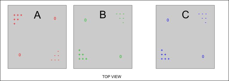
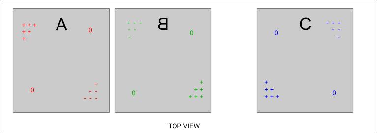
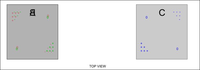
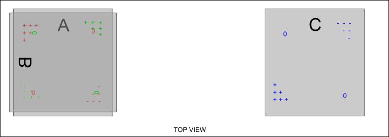
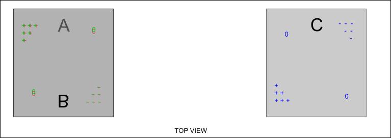
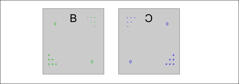
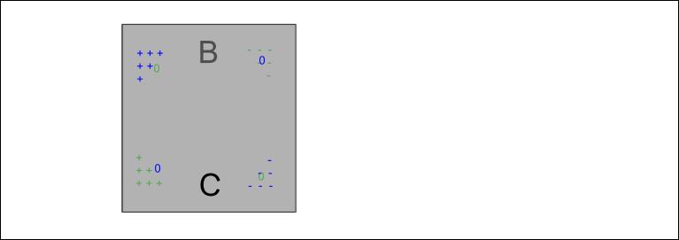
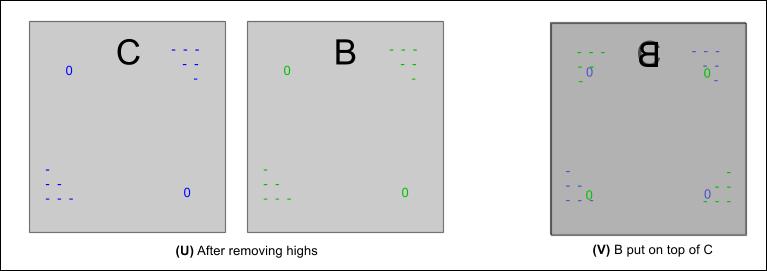
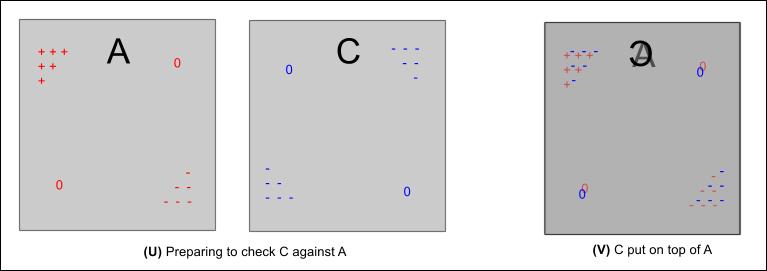
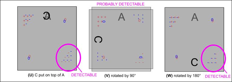
    Square or round or rectangular plate makes no difference in the final flatness provided the work is rotated a RANDOM amount. The object of rotation of the plates in successive cuts is to prevent "radial lobing" of the surface. If the plates are rotated exactly 90 degrees, 72 degrees, 60 degrees, or any other angle corresponding to a regular polygon, there is the hazard of radial "lobing" to appear in the surface. In an extreme case the surface would have the shape of the starched ruffled doily your great-grandmother may have crocheted for her dining room table. If a specific regular polygonal angle of rotation is pursued it is very possible to scrape a set of plated that print perfect but are not flat because of the radial ruffling of their surface. Thus this angle of relative rotation should be randomized from cut to cut.

    I disagree with the Moore assertion of only square or round plates being capable of generating truly flat surfaces. Square or round plate shapes may be helpful but not essential. I suspect that assertion was a bit of salesmanship via mystification. Think about it. Whitworth, Porter, Naismith, and the other luminaries of precision stimulated by the Industrial Revolution made no particular mention of square and round surface plates Vs rectangular in their writings. Neither has the lore passed down through the generations of gifted workers to us the in the present..

    I suggest we allow Wayne Moore a little BS in this one instance given his enormous contribution to mechanical precision in his lifetime.

    All is moot in these days of very acceptable granite surface plates (in compliance with the provisions of Fed Spec GGG-P-463b and current revisions) available on the used market and from import seller for low cost. The is no need to scrape three references to generate true flats when a hundred bucks will buy you an 18 x 24 granite plate flat within 0.0001" in any square foot and 0.0002" in the whole surface (YMMV depending on grade.).
    https://www.practicalmachinist.com/v...method-330634/

    Hand Scraping (For Precision Surfaces)

  8. The Following User Says Thank You to 12L14 For This Useful Post:

    Claudio HG (Jan 15, 2021)

  9. #7
    Claudio HG's Avatar
    Join Date
    Sep 2019
    Location
    Venetian Alps, EU
    Posts
    107
    Thanks
    28
    Thanked 173 Times in 48 Posts

    Claudio HG's Tools
    Thank you for those great citation and links!
    I didn't knew Forrest Addy but as I've read some from him I found he's a great source of information. This sentence (taken from a post in this thread: https://bbs.homeshopmachinist.net/fo...-hand-scraping) describe perfectly the state of mind of scraping: "Scraping and stoning is a task involving all the senses and lends itself to a Zen-like contemplation."
    LOL so true!

    What he says about rotating randomly makes perfect sense to me. I mean, I am not a machinist, nor I have that experience and skills in this field, I come from electronic engineering and computer science after all. But for that very reason the randomization makes sense to me, because it spreads the distribution of the peaks making them to fall into the average.
    That is what I've used to make my bars flat: I instinctively felt that despite rotating (flipping) the parts, it would have ended up in causing some sort of warp, so I thought that shifting the point of contact to "print" one surface against the other whould have randomized the result, or in other words made detectable the peaks and througs.
    However after having read about the rotation by 90° and the square shaped plate conditio sine qua non, I was a little bit confused because my bars resulted flat nonetheless. So I've attempted to model a simulation to get an idea of what happens ...but the devil slips in the details and I messed up my simulation.
    I think the final point can be summarized by the word detectability. If you can detect where the peaks are, then you're good to go.

    Cheers, Cld.

  10. #8
    Claudio HG's Avatar
    Join Date
    Sep 2019
    Location
    Venetian Alps, EU
    Posts
    107
    Thanks
    28
    Thanked 173 Times in 48 Posts

    Claudio HG's Tools
    I published a revised version of the video that I have taken down because it had some inaccuracies. The new video addresses those issues and provide more information on how I've made flat the ways for my home made lathe. For this I have to thanks both Johan ("DIYSwede") and "12L14" (sorry I don't know your name) for their helpful reply to my previous post. I have put an acknowdeldgment in the description of the video.
    Hope this will be useful, if it is so for you please consider to share and help me grow the channel.


    186 More Best Homemade Tools eBook

Thread Information

Users Browsing this Thread

There are currently 1 users browsing this thread. (0 members and 1 guests)

Tags for this Thread

Bookmarks

Posting Permissions

  • You may not post new threads
  • You may not post replies
  • You may not post attachments
  • You may not edit your posts
  •