
Originally Posted by
tonyfoale

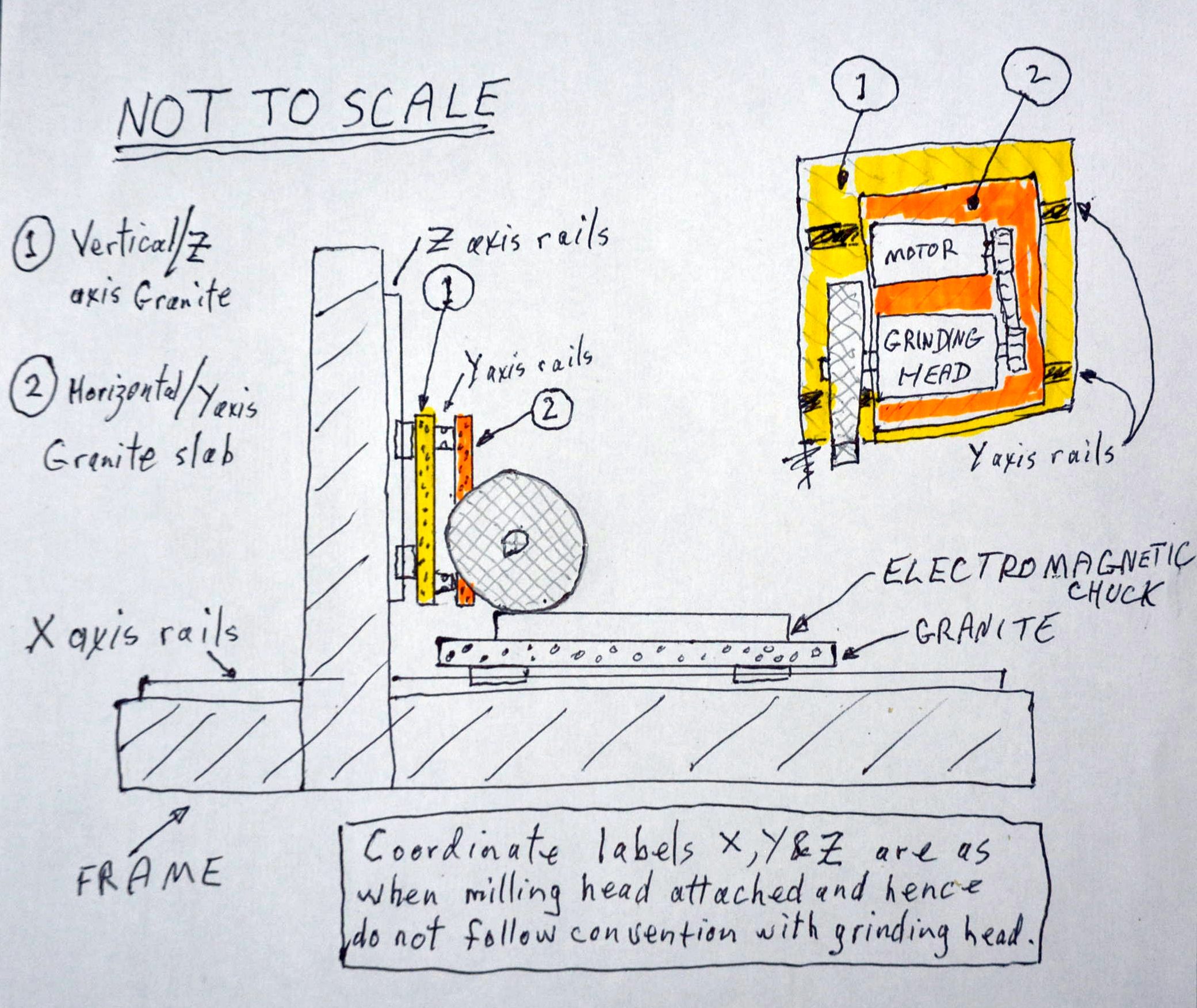
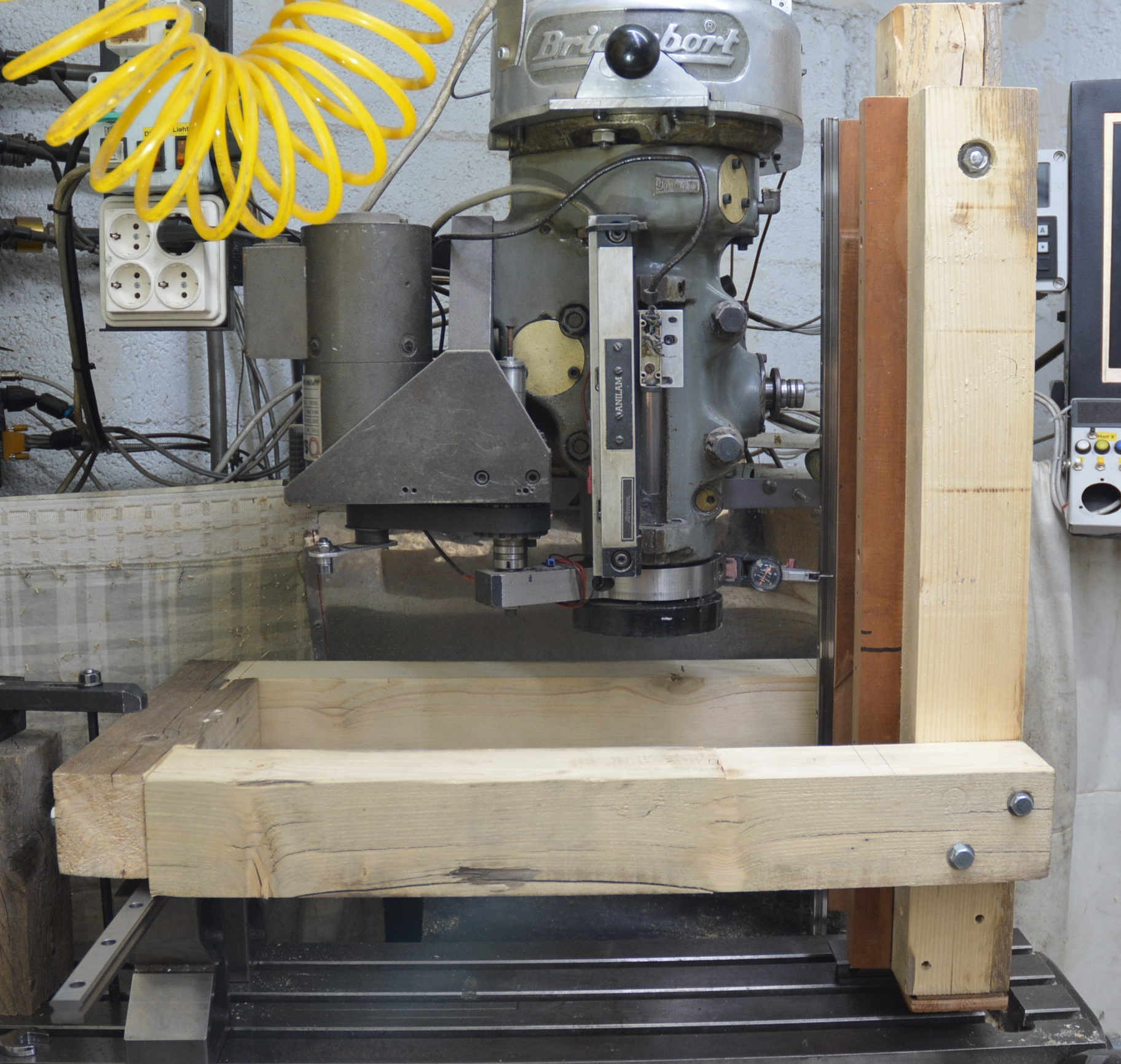
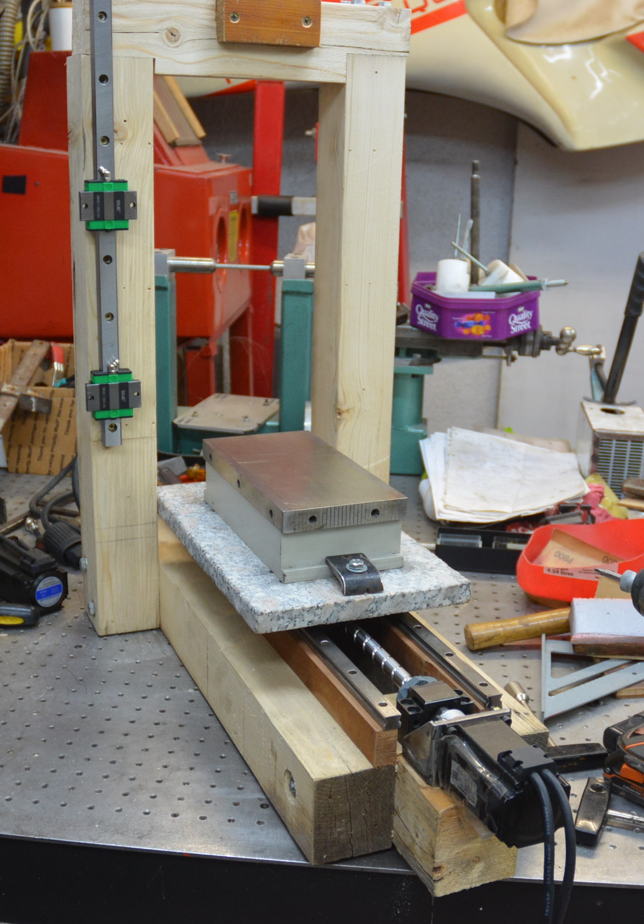
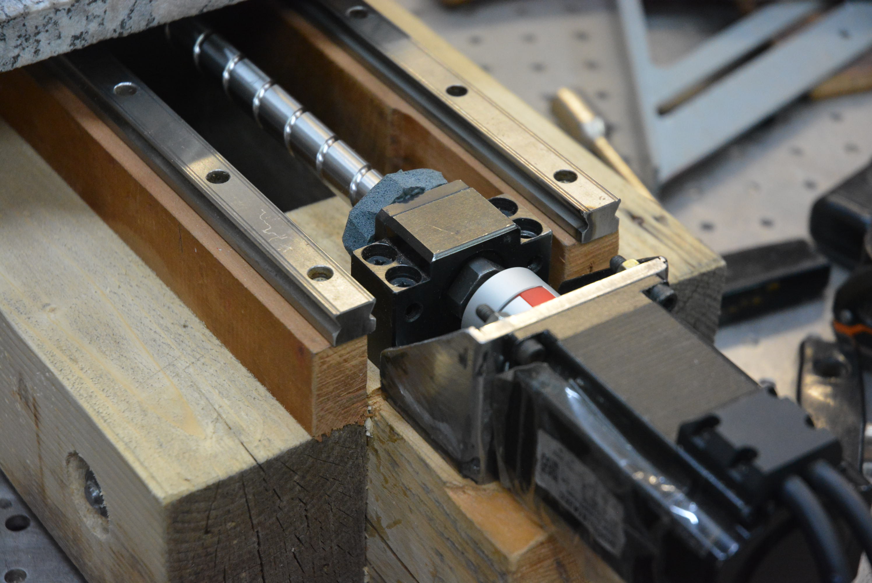
I did mention in the video that my original thoughts were to use epoxy/granite, for the frame, which I regard as superior to concrete. Neither epoxy granite nor concrete are very rigid. Just look at their Young's modulus. Both rely on steel for rigidity. For rigidity where do you get the best results from the steel? You get the best results when the steel is at the surface. Just consider their I, moments of inertia. Hence my choice of steel tube filled with epoxy granite. In addition it is so much easier to make.

 LinkBack URL
 About LinkBacks


 Reply With Quote


Bookmarks