Free 186 More Best Homemade Tools eBook:  
Get 2,000+ tool plans, full site access, and more.

User Tag List

Page 3 of 4 FirstFirst 1 2 3 4 LastLast
Results 21 to 30 of 37

Thread: Home built Heat Treating Oven

  1. #21
    CanBeDone's Avatar
    Join Date
    Oct 2019
    Posts
    43
    Thanks
    0
    Thanked 38 Times in 18 Posts
    Quote Originally Posted by anthonyget View Post
    Thanks for your feedback. I would be interested to know where I should have placed my element and thermocouple. Although I think Fink's law might be a tad over my head.
    First: Why use an electric furnace, since an electric furnace is so much slower in heating up than is a gas-fired one, or even a coke-fired forge? To me, there is only one answer, and that is temperature control. If you build a furnace to heat treat knives, you would want an area inside your furnace that deviates no more than 10oC from the set temperature. A PID controller has no problem controlling a temperature to within 1oC, but does so only if the thermal conductivity of your furnace material can be disregarded, i.e. is large enough that the furnace has the same temperature anywhere, inside and outside. Since this is not the case, this means you have no freedom to choose where you place your controlling thermocouple. Its tip has to be where the furnace is hottest, i.e. right next to your heating wire, and somewhat further back than the middle of the furnace, since a furnace is bound to be coldest on the side of the door.
    It is also a good idea to position the tube, inside which the thermocouple rests, parallel to the longest extent of the furnace, since accurate positioning of the rather flexible thermocouple is not that easy, and why make it difficult to yourself?

    Second: Wikipedia is too restrictive when it describes Fick's laws as laws for diffusion only. Actually, the equations are valid for all sorts of transport phenomena, from how many cars can travel on a road, to how a balloon discharges through its nozzle, to - what I am interested in here - how heat travels through matter. A caution, though: it is the simplest possible description of transport phenomena, and as such does not account for things like melting or turbulence.
    Because the mathematical description is the same, it is possible to visualize heat transport as a fluid transport:
    Attachment 35328
    In this drawing - limited by the capabilities of my CAD program - red stands for a fluid being pumped into a vessel (white) that is open at the top. Inflow and outflow pipes are separated by a baffle (also white) so that any fluid momentum is broken up and need not be considered. Under these circumstances, the total volume of fluid in the vessel may be taken as a representation of the heat inputted into the furnace, and the height of the fluid column as its temperature.
    That is the global picture, and it assumes that heat (and fluid) travels everywhere at infinite speed. This is, of course, not true. The furnace walls act as insulators, to slow down the flow of heat and that needs to be accounted for.
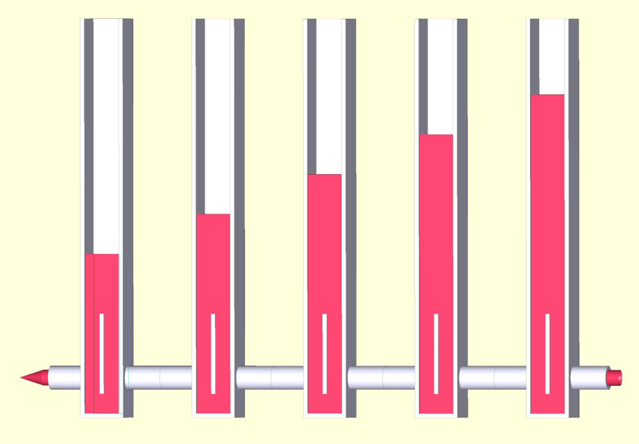
    We do this by representing the furnace not as a single vessel, but many vessels connected in series parallel, and the limited travel speed of heat / fluid by a suitable small diameter of the inflow / outflow pipes:
    Attachment 35329
    This picture represents a cross-section through a furnace wall, and because the connecting pipes are suitably small, friction inside the pipes degrades the pressure available to uphold the length of the columns (the temperature) for each component vessel.

    Third: Under this heading belongs the expansion of what has been said so far into three dimensions. This I will leave unsaid for today, as I will leave unsaid
    Fourth: Implications for the placement of heating wires and furnace bricks,
    giving you opportunity to mull things over and discover for yourself some of the consequences of what I have written so far. After all, my objective is not to tell you how to do it, but to enable you to find out for yourself.

    186 More Best Homemade Tools eBook

  2. #22
    CanBeDone's Avatar
    Join Date
    Oct 2019
    Posts
    43
    Thanks
    0
    Thanked 38 Times in 18 Posts
    Somehow - I suspect because my contribution got too long - my pictures got stripped. Here they are again:
    First picture: Home built Heat Treating Oven-whatistemp.jpeg
    Second picture: Home built Heat Treating Oven-whatistemp2.jpeg

    2000 Tool Plans

  3. #23
    DanCom's Avatar
    Join Date
    Dec 2016
    Posts
    14
    Thanks
    1
    Thanked 17 Times in 7 Posts
    Nick,

    I work with stainless and it has a prescribed "soak" temperature and time to hold at to ensure the carbon is in solution. For 1084, I get it to critical temp, wait a couple of minutes and then quench. For O1, I hold at critical temp for 10 minutes, then quench. Each steel has its own recipe if you will. Steel manufacturers like Sandvik and Crucible prescribe soak times based in the thickness of the steel. E.g. hold at x temperature for y minutes per cm of of thickness. This is because the outside of the steel heats faster than the inside. Another step in the heat treatment process is "equalization." This is a rest period to ensure uniform temperature in the piece. As my oven ramps fairly slow, and 'am usually using thin steel (3mm or less), I often skip the equalization step as the steel is roughly the same temperature as the air in the oven. A fast heating oven will have the interior temperature rising faster than the steel. Fast ramping and thick steel will require longer equalization and soak periods.

    There's plenty of room for experimentation as each oven will behave in a slightly different way. Placement of the thermocouple will impact the readings somewhat. I place my thermocouple through the bottom as close as possible to the blade rack. Really what I want is the temperature of the steel and not the temperature of the air in the top of the oven. Make sense?

    Also, run the Autotune on the controller if you haven't already.

    Cheers,

    Dan

  4. #24
    Supporting Member anthonyget's Avatar
    Join Date
    Oct 2019
    Location
    Kelmarsh, UK
    Posts
    89
    Thanks
    29
    Thanked 153 Times in 42 Posts

    anthonyget's Tools
    Quote Originally Posted by DanCom View Post
    Nick,

    I work with stainless and it has a prescribed "soak" temperature and time to hold at to ensure the carbon is in solution. For 1084, I get it to critical temp, wait a couple of minutes and then quench. For O1, I hold at critical temp for 10 minutes, then quench. Each steel has its own recipe if you will. Steel manufacturers like Sandvik and Crucible prescribe soak times based in the thickness of the steel. E.g. hold at x temperature for y minutes per cm of of thickness. This is because the outside of the steel heats faster than the inside. Another step in the heat treatment process is "equalization." This is a rest period to ensure uniform temperature in the piece. As my oven ramps fairly slow, and 'am usually using thin steel (3mm or less), I often skip the equalization step as the steel is roughly the same temperature as the air in the oven. A fast heating oven will have the interior temperature rising faster than the steel. Fast ramping and thick steel will require longer equalization and soak periods.

    There's plenty of room for experimentation as each oven will behave in a slightly different way. Placement of the thermocouple will impact the readings somewhat. I place my thermocouple through the bottom as close as possible to the blade rack. Really what I want is the temperature of the steel and not the temperature of the air in the top of the oven. Make sense?

    Also, run the Autotune on the controller if you haven't already.

    Cheers,

    Dan
    Thanks so much Dan. So i have worked out that my reading is about 100C out and realised that the tip of my probe was in perfect line with the elements which cant be good. Thanks so much for all the good advice and the best blog. I made your belt grinder by the way. Very grateful for your sharing so much know how.

  5. #25
    Supporting Member anthonyget's Avatar
    Join Date
    Oct 2019
    Location
    Kelmarsh, UK
    Posts
    89
    Thanks
    29
    Thanked 153 Times in 42 Posts

    anthonyget's Tools
    Well for any of you who have had the stamina to stay with me, here is the third and final part of my build.
    Thank you to all of you who have helped and given me so much help. Not perfect but I usable and will be used a lot.


  6. The Following 4 Users Say Thank You to anthonyget For This Useful Post:

    Eaglewood (Jun 18, 2020), high-side (Jun 19, 2020), Jon (Jun 18, 2020), mwmkravchenko (Jun 18, 2020)

  7. #26
    Content Editor
    Supporting Member
    DIYer's Avatar
    Join Date
    Aug 2013
    Posts
    3,057
    Thanks
    771
    Thanked 1,850 Times in 1,652 Posts


    Thanks anthonyget! We've added your Heat Treatment Oven to our Heating and Cooling category,
    as well as to your builder page: anthonyget's Homemade Tools. Your receipt:


  8. #27
    Supporting Member
    Join Date
    Aug 2016
    Posts
    635
    Thanks
    1
    Thanked 187 Times in 166 Posts

    wizard69's Tools
    I kinda wish that I had seen this thread earlier as I've worked on validating a number of process ovens and probably could have pointed out a few things of note. The first thing to point out is that unless you have active circulation in an oven the temperature in that oven will vary throughout. Even with fan driven circulation it is a real challenge to get the temperature profiles in an oven within spec.

    For heat treat ovens of this type active circulation isn't going to happen so you will have to expect varying temperature profiles. You can actually get variations of a surprising amount which leads to the age old problem of where do you put the thermocouple This isn't as easy as you might at first imagine. For example, at first blush you might want to put the probe next to the mass being treated, however until that mass gets up to temperature it will skew your readings as it effectively acts as a heat sink. The bad thing here is that that can lead to over heating elsewhere in the oven. How bad this will be depends upon many factors (one big factor is the mass followed by how close the TC is to that mass) but could lead to damage in high heat areas.

    Since heat rises and the items being treated generally lie on or near the bottom of the oven, you may want to consider TC entry from the side walls below the heater element. Ideally your TC is adjustable for depth thus allowing you to find an optimal location. By the way the bricks will also act somewhat like a heat sink, they are of course thermal insulators, but they do take time to heat up thus impacting the oven profile. So you don't want the TC too close to any fire brick.

    As for your temperature controller realize that the only thing it knows about is the temperature seen at the exact point of where the TC junction is. Without active circulation it is safe to say that the temperature varies a lot every where else in the chamber. You do get some circulation from convection and air infiltration but air infiltration just makes the temp profile worse. So sealing against air infiltration can do wonders for addressing the high variability in the temperature profile in the oven. In the case of this oven that means sealing the door with some sort of high temp solution.

  9. The Following User Says Thank You to wizard69 For This Useful Post:

    anthonyget (Jul 13, 2020)

  10. #28
    Supporting Member anthonyget's Avatar
    Join Date
    Oct 2019
    Location
    Kelmarsh, UK
    Posts
    89
    Thanks
    29
    Thanked 153 Times in 42 Posts

    anthonyget's Tools

    Fixing my mistakes

    Hi Johan,
    You were so right about a lot of things. I have had to rebuild most of my oven. I wanted to thank you for your advice.
    This is what makes these blogs so generous. Thanks again.


  11. The Following 2 Users Say Thank You to anthonyget For This Useful Post:

    DIYSwede (Jul 13, 2020), Jon (Jul 11, 2020)

  12. #29
    Supporting Member anthonyget's Avatar
    Join Date
    Oct 2019
    Location
    Kelmarsh, UK
    Posts
    89
    Thanks
    29
    Thanked 153 Times in 42 Posts

    anthonyget's Tools
    Thanks Wizard, the learning curve on this one has been pretty steep.

  13. #30
    Supporting Member
    Join Date
    Oct 2016
    Posts
    1,113
    Thanks
    25
    Thanked 345 Times in 242 Posts

    old kodger's Tools
    Not wishing to teach my granny to suck eggs, and I hope my comments are relevant. Many years ago, a company called "tor gem" made a solid fuel stove (heater)
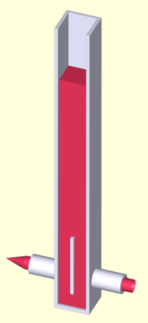
, that had mica windows in the front I used to burn furnacite beads in it, they get very hot, and the result was that over time the mica "delaminated" and went hazy, not important in the stove, I only needed to see that it was glowing nicely, but where you need to see a process, that might be important.
    I don't know if this is normal, but if it is you might want to design your door to be able to replace the mica without destroying the build.

Thread Information

Users Browsing this Thread

There are currently 2 users browsing this thread. (0 members and 2 guests)

Tags for this Thread

Bookmarks

Posting Permissions

  • You may not post new threads
  • You may not post replies
  • You may not post attachments
  • You may not edit your posts
  •