
 LinkBack URL
 About LinkBacks

 I took his idea a step further: Izzys design uses a store-bought worm and spur gear mechanism, while I used an old car-wiper motor to create vertical movement based on the Scotch yoke principle "Pin It")
Newbie here - first post!
For years, I have been thinking of building an oscillating spindle sander using only a single motor, unlike all the models that I saw, which use two motors.
Recently, I happened to see Izzy Swan's machine (thanks, Izzy!) I took his idea a step further: Izzys design uses a store-bought worm and spur gear mechanism, while I used an old car-wiper motor to create vertical movement based on the Scotch yoke principle.
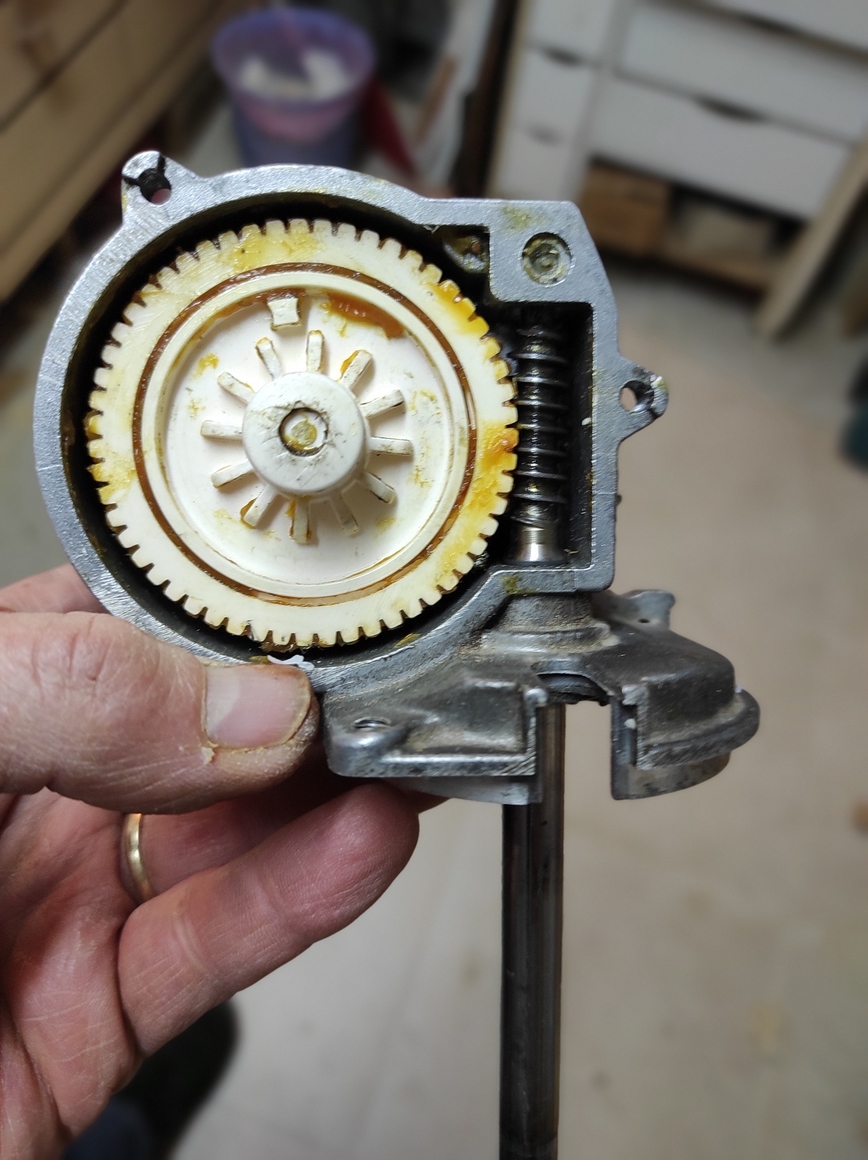
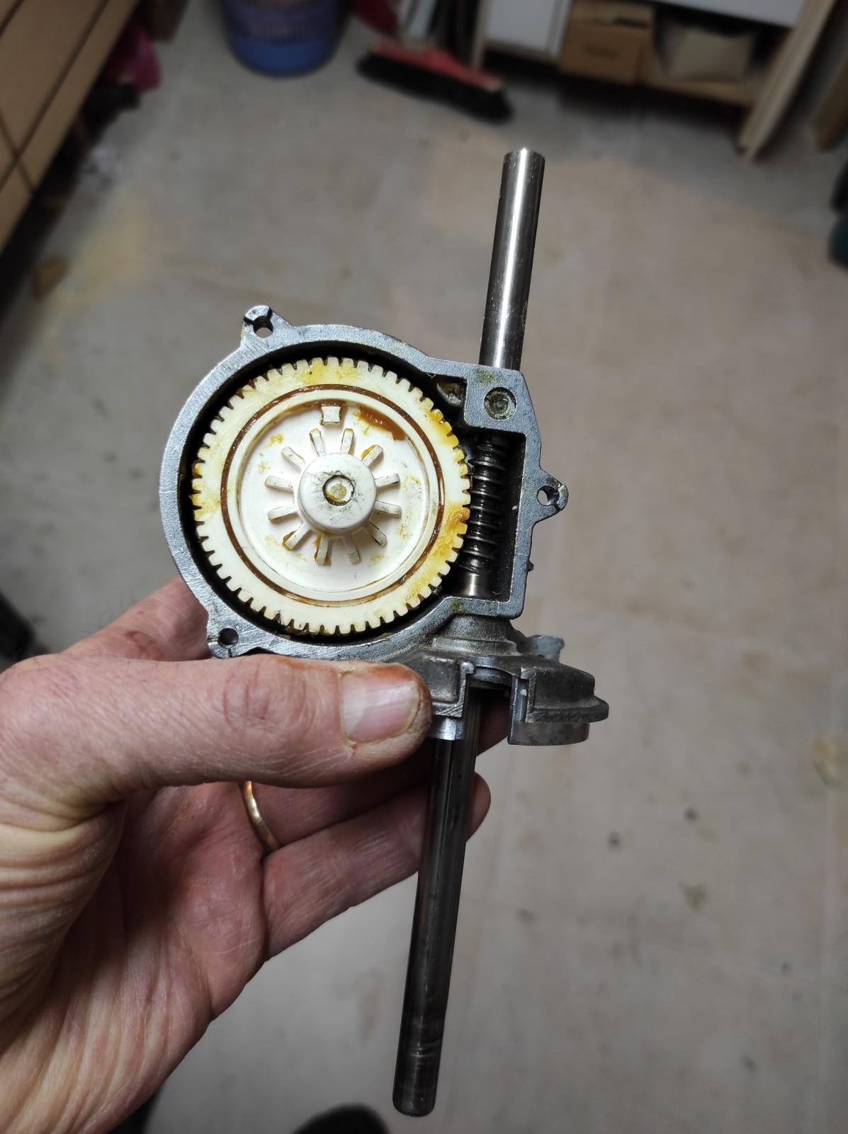
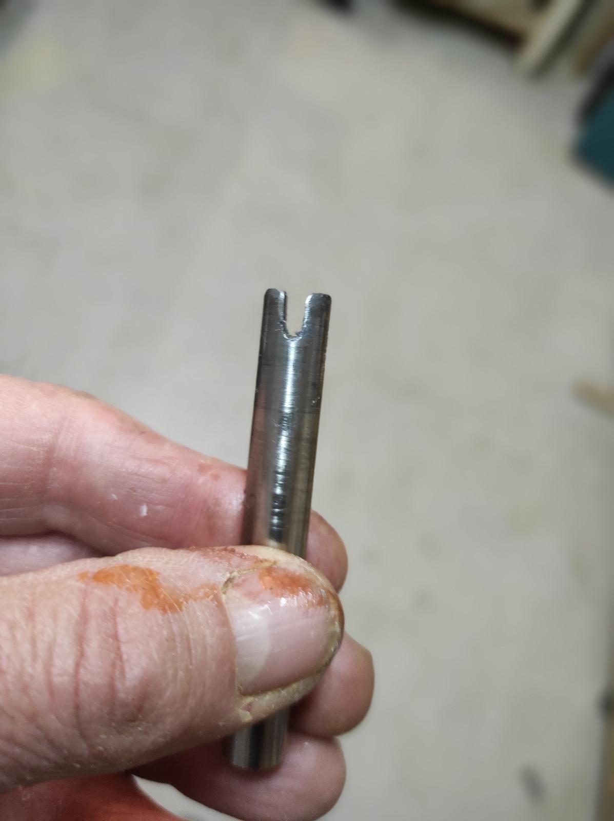
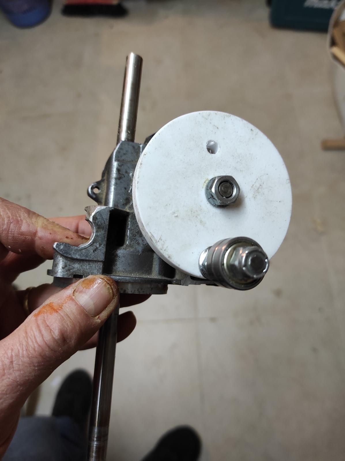
I stripped the motor from all the electric components (magnet, wires etc.) leaving only the worm shaft and the spur gear. However, I now had a problem. In Izzy's machine, the shaft goes into the case and out the other side, and then connected to the sanding drum, but in my ex-motor the worm-shaft ends up touching the spur gear. I solved it by drilling a 9.5mm hole in the upper part of the case, through which I inserted a 9.5mm steel rod salvaged from a dead printer. The two rods (the incoming one and the outgoing) engage with each other using a slot cut in one of them and a pin inserted to the other. I used the same method to engage the upper rod with the sanding drum, making it very easy and quick to replace the drum. I threaded the upper part of the extension rod to accommodate the fastener that locks the drum to the rod.
The photos show some steps of the construction process, and the clip tells the whole story. I hope you enjoy it as much as I did.
Photos:
- Worm shaft original length
- Worm shaft + extension
- A slot cut in the upper rod to engage the pin in the lower one
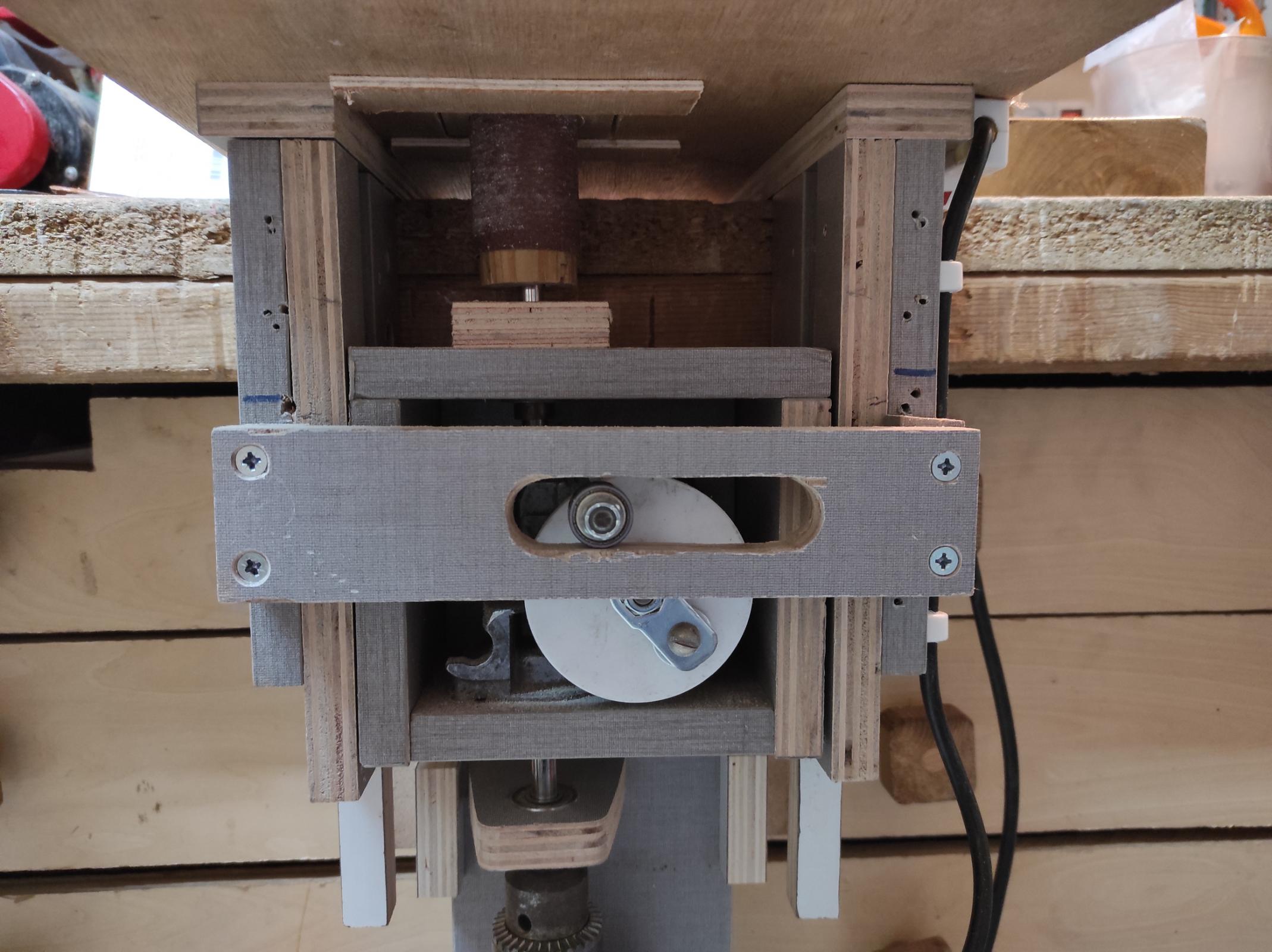
- Scotch yoke wheel and ball bearings to reduce friction.
- Front view


 Reply With Quote

Bookmarks