Free 186 More Best Homemade Tools eBook:  
Get 2,000+ tool plans, full site access, and more.

User Tag List

Results 1 to 10 of 10

Thread: Hougen mag drill with Broken Spindle

  1. #1
    Supporting Member hemmjo's Avatar
    Join Date
    Feb 2017
    Posts
    2,551
    Thanks
    226
    Thanked 1,449 Times in 822 Posts

    hemmjo's Tools

    Hougen mag drill with Broken Spindle

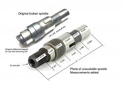
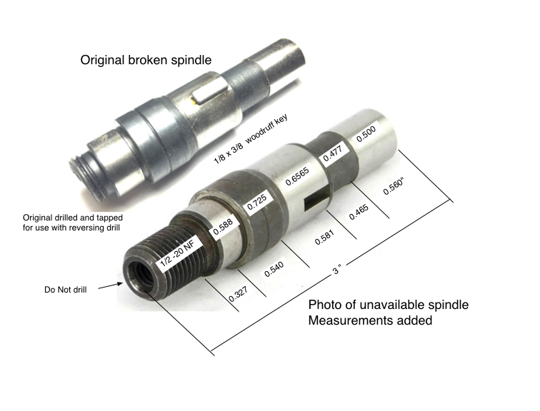
    I got an old Hougen magnetic base portable drill press with a broken spindle. The part is obsolete. I have searched extensively online for a replacement with no luck.

    It is just a shaft with a couple of different diameters, 1 threaded end and a Woodruff key seat. It has a couple of precision ground spots that run in needle bearings. Those will be the most challenging for me. I am game to try it with my tool post grinder. The original is drilled and taped as you would use on a reversing drill, but this one does not reverse. Since the original broke in the threads, I am planning to leave the threaded end of the spindle solid for additional strength. The original is broken clean, very fine grain with no distortion. I am sure it was heat treated.

    From what I have read so far, A-2 tool steel appears to be and appropriate material. I assume the original was heat treated, but I have no idea how much to temper it.

    I have confidence I can do all of the required machine operations. I plan to turn the rough sizes, maybe +0.005" then heat treat and finish the critical sizes by grinding.

    I have basic treating capability which I have used for chisels and cutting tools etc. I am thinking the most critical heat treat operation will be how much to temper the part.

    Any heads up will be appreciated.

    Hougen mag drill with Broken Spindle-broken-spindle.jpg

    186 More Best Homemade Tools eBook

  2. The Following 2 Users Say Thank You to hemmjo For This Useful Post:

    mwmkravchenko (Aug 31, 2022), Scotty1 (Sep 3, 2022)

  3. #2
    Supporting Member metric_taper's Avatar
    Join Date
    Mar 2017
    Location
    Marion, Iowa
    Posts
    585
    Thanks
    228
    Thanked 257 Times in 153 Posts

    metric_taper's Tools
    I think that air hardening tool steel will be too hard, and like glass, so very brittle. Improper tempering may be the cause of the failure.

    I made a repair many years ago of a 3/4" shaft that had needle bearings running on that surface. This was in a reduction gear box on my Gehl 2500 skid steer.
    Oil hardening tool steel is what I used. I tempered it back in an oil bath using a camping stove (didn't want oil at that temp on the stove inside the house). Tempering temp was 400F for 15 minutes. I happen to have a heat treat furnace (purchase because of that project). Your part is rather large. So heating evenly to the critical temp needs to be addressed.

    2000 Tool Plans

  4. The Following User Says Thank You to metric_taper For This Useful Post:

    hemmjo (Sep 2, 2022)

  5. #3
    Supporting Member hemmjo's Avatar
    Join Date
    Feb 2017
    Posts
    2,551
    Thanks
    226
    Thanked 1,449 Times in 822 Posts

    hemmjo's Tools
    I appreciate your input. I am not arguing the point, just discussing it.

    From my experience tempering is the easiest part of the process to get right if you know the desired temperature desired. From my research it seems that 950˚f is about right. It seems that most parts that are ruined the damage occurs during hardening when quenching.

    I actually have a piece of 0-1 tool steel, but it is only 0.625 diameter. If I have to buy something, I may as well buy the correct material.

    There is so much information available it is just a bit over whelming to digest it all. This for example appears to be a good general explanation for types of tool steel.

    This chart is a summary at the end of the above link.
    Hougen mag drill with Broken Spindle-tool-steel-types.png

    Another site gives specific temperatures for various types of tool steel. I see this for A-2;

    "TEMPERING
    The tempering temperature may be varied according to the desired hardness. If maximum hardness is desired, tempering should be in the range of 300-400F, but if a lower hardness is acceptable, tempering at 950F will give the optimum combination of hardness and toughness."

  6. #4
    Supporting Member metric_taper's Avatar
    Join Date
    Mar 2017
    Location
    Marion, Iowa
    Posts
    585
    Thanks
    228
    Thanked 257 Times in 153 Posts

    metric_taper's Tools
    I have some silver steel in oil and water hardening that I stock.
    I've run into air hardening accidentally a few times with mystery metal I got from surplus. I was machining away, and the material got hot and self hardened before I got finished. It didn't get that hot. That ended up scrapping the part, one time I broke a tap off. I have used my heat treat furnace to anneal tool steels so I could repair some part of them, then heat treat them again (and I've removed broken taps that way). For oil hardening, the 400F was the desired temp for a bearing surface.

    I did make a draw bar for the band saw (blade tensioning), as the original metric bolt they used had thread failure (just soft no grade bolt). So I had a piece of oil hardening rod in the right diameter, ran the die on it, then heat treated it, so the threads did not get buggered up again. I did not temper, it snapped during band tightening, so I remade it and tempered it. It was one of those cheap imports 6x4 bandsaws. I didn't think tempering would be needed.

    I believe that air hardening would be for cutting tools, you may make it work for this application. But you have lots of machining to do. The oil hardening does expand on hardening, memory is about .002/inch of material. Should not be a problem if you do the final grinding with tool post grinder on your lathe, as you're leaving material to grind to the bearing fit.

    I just have a can of either engine oil or vegetable oil, they bot seem to work. But I'm no expert in making a long shaft that is straight when done.

  7. The Following User Says Thank You to metric_taper For This Useful Post:

    hemmjo (Sep 2, 2022)

  8. #5
    Supporting Member Toolmaker51's Avatar
    Join Date
    Feb 2016
    Location
    Midwest USA
    Posts
    5,331
    Thanks
    7,042
    Thanked 2,980 Times in 1,893 Posts

    Toolmaker51's Tools
    Sent PM with my spin and contact info..........the above suggestions are correct. "A-2" is primarily steel for punches and dies on lesser abrasive materials, "D" is very abrasion resistant, including grinding or resharpening a dieset. They like staying straight, can't picture them suitable for keyed or thread-relieved rotating parts. Chrome Moly Cr would be my choice; good enough for racing axles, so...... and machines nicely. Unsure regarding torque of a mag-drill and bigger annular cutters, some calculations x cross section might allow Stress Proof.
    While different companies give the steels various 'names' the SAE-ASTM standards make the products very comparable. Most listings incorporate a conversion.
    Sincerely,
    Toolmaker51
    ...we'll learn more by wandering than searching...

  9. The Following User Says Thank You to Toolmaker51 For This Useful Post:

    hemmjo (Sep 2, 2022)

  10. #6
    Supporting Member Toolmaker51's Avatar
    Join Date
    Feb 2016
    Location
    Midwest USA
    Posts
    5,331
    Thanks
    7,042
    Thanked 2,980 Times in 1,893 Posts

    Toolmaker51's Tools
    To "metric-taper" post *4, import or not, band tension exerts lots of tensile stress and torsional to a lesser degree on that threaded shaft, on not a big cross section. They can heat treat a bundle of shafts cheaper than making of substantial size or material.
    Sincerely,
    Toolmaker51
    ...we'll learn more by wandering than searching...

  11. #7
    Supporting Member metric_taper's Avatar
    Join Date
    Mar 2017
    Location
    Marion, Iowa
    Posts
    585
    Thanks
    228
    Thanked 257 Times in 153 Posts

    metric_taper's Tools
    Quote Originally Posted by Toolmaker51 View Post
    To "metric-taper" post *4, import or not, band tension exerts lots of tensile stress and torsional to a lesser degree on that threaded shaft, on not a big cross section. They can heat treat a bundle of shafts cheaper than making of substantial size or material.
    Toolmaker; My cheap 4x6 bandsaw was made in 1976 in Taiwan, when they were still making mass produced junk. Still see the same design errors in new ones. That original tensioning bolt was a cheap hex bolt with a knob molded onto the hex head.
    I used 7/16" O2 round stock to make the replacement, I changed the thread from metric to inch standard as I made a new female mate (as it was in bad shape). I also installed a thrust bearing as I had one laying about (took the saw apart so I could machine a flat on what was a cast iron surface with the pattern relief angle preventing a square surface for this function), and it's really a missing part (even on my Ellis 1600 bandsaw). On that note, thrust bearings are missing on the draw bolt for the milling machine, which I added to pull the R8 collet in on my Wells-Index mill, and I made one for my antique Rockford horizontal mill (uses #9 Brown and Sharp taper). On the vertical mill, I used a knurled piece of 3" round stock, 2" long to replace the hex nut that the original had. I find I can hand tighten that and get the R8 pulled in with hand force, I do use a rubber strap wrench if needed to give a bit more torque. That thrust bearing makes all the difference. I know people will think I'm crazy as you must use some long arm wrench to tighten these draw bolts. But I've not found it to be a problem in 30 years. I used the clutch throw out bearing from my 1981 Datsun B210 for the vertical mill.

  12. #8
    Supporting Member Toolmaker51's Avatar
    Join Date
    Feb 2016
    Location
    Midwest USA
    Posts
    5,331
    Thanks
    7,042
    Thanked 2,980 Times in 1,893 Posts

    Toolmaker51's Tools
    Quote Originally Posted by metric_taper View Post
    Toolmaker; My cheap 4x6 bandsaw was made in 1976 in Taiwan, when they were still making mass produced junk. Still see the same design errors in new ones. That original tensioning bolt was a cheap hex bolt with a knob molded onto the hex head.
    I used 7/16" O2 round stock to make the replacement, I changed the thread from metric to inch standard as I made a new female mate (as it was in bad shape). I also installed a thrust bearing as I had one laying about (took the saw apart so I could machine a flat on what was a cast iron surface with the pattern relief angle preventing a square surface for this function), and it's really a missing part (even on my Ellis 1600 bandsaw). On that note, thrust bearings are missing on the draw bolt for the milling machine, which I added to pull the R8 collet in on my Wells-Index mill, and I made one for my antique Rockford horizontal mill (uses #9 Brown and Sharp taper). On the vertical mill, I used a knurled piece of 3" round stock, 2" long to replace the hex nut that the original had. I find I can hand tighten that and get the R8 pulled in with hand force, I do use a rubber strap wrench if needed to give a bit more torque. That thrust bearing makes all the difference. I know people will think I'm crazy as you must use some long arm wrench to tighten these draw bolts. But I've not found it to be a problem in 30 years. I used the clutch throw out bearing from my 1981 Datsun B210 for the vertical mill.
    It's clear what degree of trust metric_taper places on thrust, with amount of thrust his post carries..
    Bad puns aside, that mechanical aspect is so often neglected or not even considered. I've lapped hard washers to gain that security on torqued fasteners; those being repeatedly loosened need it most of all. Any burr or dirt scores mating surfaces, requiring increased tightening for retention. Easily cured with various efforts of lapping, and a bit of high pressure lube.
    My long-time go to mill wrench are double box ends, 3/4" and 7/8" in the case of running a Bridgeport pattern. 3/4" does the drawbar and sometimes handy operating the vise, along with convenient parking between operations, and 7/8" for clamping hardware, another handy parking spot.
    A neophyte operator watched me, next day had same wrench as I........, but lacked some discretionary finesse.

    But I've never sheared a drawbar. I told him so, adding that wrench lengths are coordinated to sizes of related fasteners; not the requirement to use all of it!
    Sincerely,
    Toolmaker51
    ...we'll learn more by wandering than searching...

  13. #9
    Supporting Member metric_taper's Avatar
    Join Date
    Mar 2017
    Location
    Marion, Iowa
    Posts
    585
    Thanks
    228
    Thanked 257 Times in 153 Posts

    metric_taper's Tools
    Quote Originally Posted by Toolmaker51 View Post
    It's clear what degree of trust metric_taper places on thrust, with amount of thrust his post carries..
    Bad puns aside, that mechanical aspect is so often neglected or not even considered. I've lapped hard washers to gain that security on torqued fasteners; those being repeatedly loosened need it most of all. Any burr or dirt scores mating surfaces, requiring increased tightening for retention. Easily cured with various efforts of lapping, and a bit of high pressure lube.
    My long-time go to mill wrench are double box ends, 3/4" and 7/8" in the case of running a Bridgeport pattern. 3/4" does the drawbar and sometimes handy operating the vise, along with convenient parking between operations, and 7/8" for clamping hardware, another handy parking spot.
    A neophyte operator watched me, next day had same wrench as I........, but lacked some discretionary finesse.

    But I've never sheared a drawbar. I told him so, adding that wrench lengths are coordinated to sizes of related fasteners; not the requirement to use all of it!
    The previous owner of the mill abused the hell out of the original OEM drawbar assembly. The Wells-Index has a thread spigot on the end of the spindle where the sliding quill splines end. This threaded end is where the thrust flat plate is threaded on, for the drawbar bolt, washer to pulled against. I had to make a new one, and made it to fit the thrust bearing diameter. It's worked well, I've not had any of the end mill adapters, face mills, boring heads or collets ever let the tools spin. I did design it that if needed I could put a hex on the assembly, but found it was not needed.
    You making a living doing this, see the need for the use of more torque.
    A bigger issues is the spline is worn, and that will make pounding sounds in some sections of the quill travel where the wear is worse. I really only ever use the mill to repair things, so it's not a production used machine.
    I do have a good sense of torque vs fastener max stress. It's been a long time since I twisted any bolt hardware off.

  14. The Following User Says Thank You to metric_taper For This Useful Post:

    Toolmaker51 (Sep 9, 2022)

  15. #10
    Supporting Member Toolmaker51's Avatar
    Join Date
    Feb 2016
    Location
    Midwest USA
    Posts
    5,331
    Thanks
    7,042
    Thanked 2,980 Times in 1,893 Posts

    Toolmaker51's Tools
    Use of the long wrench lends good torque feel. If were to guess that might approach 40 ft-lbs. Next to wrong tool diameter causing sprung collets, leading to stripped threads, excess torque goes there straightaway. The spindle key and collet slot what makes all of it work. I wipe the spindle and holder tapers every time. Probably 30% my holders are collets, normal fractions only. Remainder are solid; Morse Taper, endmill holders, QC, Jacobs. tap drivers etc. They eat a bit extra daylight, but the littlest tap of drawbar drops them out.


    186 More Best Homemade Tools eBook
    Sincerely,
    Toolmaker51
    ...we'll learn more by wandering than searching...

Thread Information

Users Browsing this Thread

There are currently 1 users browsing this thread. (0 members and 1 guests)

Bookmarks

Posting Permissions

  • You may not post new threads
  • You may not post replies
  • You may not post attachments
  • You may not edit your posts
  •