
 LinkBack URL
 About LinkBacks


For some time I have been planning to change the single phase, single speed motor on my lathe for a larger 3 phase motor driven by a VFD (Variable Frequency Drive). The infinitely variable motor speed would allow me to eliminate the multiple pulley speed change system, but there is a problem when running a motor at low speed with a VFD. For a given spindle speed the spindle torque from a motor running at slow speed is less than achieving the same slow speed by mechanical gearing, for a given motor. A way around this problem is to use a vastly oversize motor.
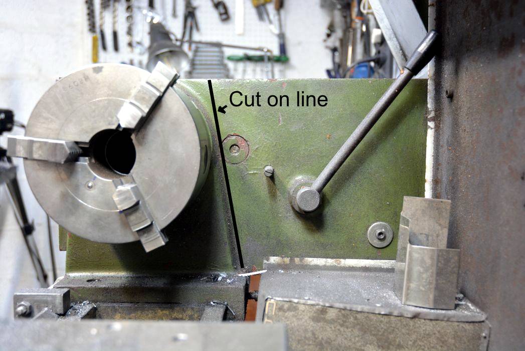
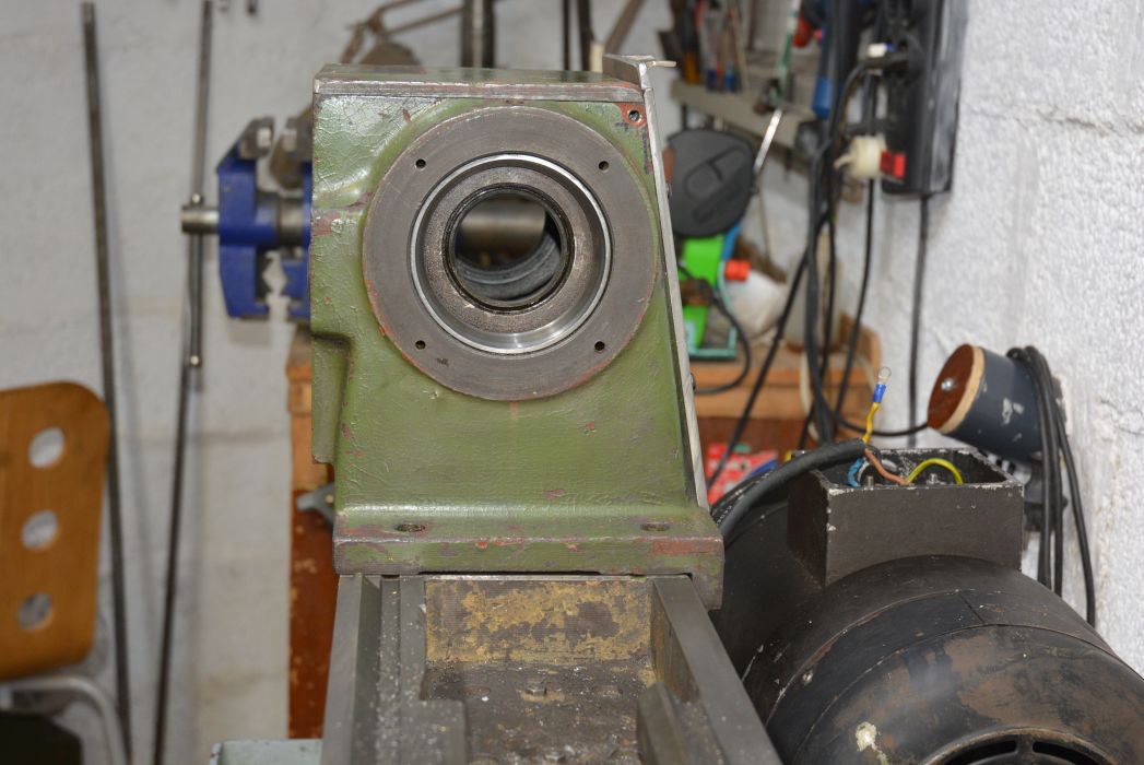
This post is not about fitting the motor but is about some changes to the lathe head that the motor and drive system enabled me to do. My motivation was to make the head stiffer and less prone to vibration and chatter. Not that I had particular problems in that area but I find it hard to resist when I see a better way of doing something.
Although I show how I did this on my lathe, a 1240 JET, the ideas are certainly applicable to those lathes which do not have a closed in spindle head.

Click images for full size.
I have prepared a PDF file with all the reasoning and details at Inflicting GBH on a lathe
I plan to put together a video about this but in the meantime here is a link to a 2 minute video showing some stiffness measuring.
https://www.dropbox.com/s/7t7ho5x1qq...Lathe.mp4?dl=0
Warning: The pdf shows images of severe GBH to a lathe and those with extreme sensitivity to mechanical abuse are advised to look away now.


 Reply With Quote

Bookmarks