Free 186 More Best Homemade Tools eBook:  
Get 2,000+ tool plans, full site access, and more.

User Tag List

Page 2 of 2 FirstFirst 1 2
Results 11 to 14 of 14

Thread: Improving lathe turning accuracy.

  1. #11
    Supporting Member Toolmaker51's Avatar
    Join Date
    Feb 2016
    Location
    Midwest USA
    Posts
    5,331
    Thanks
    7,042
    Thanked 2,981 Times in 1,893 Posts

    Toolmaker51's Tools
    Tony's 5.74 decimal degrees [or 5° 44' 24"] produces a geometric .0001 movement of the compound; actual movement is theoretical depending on accuracy of dial and thread pitch built into lathe. As he states, an indicator resolve better than the screw & dial alone.

    The problem's root? Conversion of manual torque overcoming stiction to rotary motion [screw & dial] into the linear of any slide motion. Add counteracting manufacturing tolerances of equipment itself...

    Unless your lathe has [a]very large diameter dials, [b]a vernier, [c]gibs and [d]backlash well set, and [e]screw/ nut combination are very smooth operating, such fine increments are difficult to attain. A 1/10th by lathe cross slide is virtually impossible; while a good old jig bore can do that with no fuss; utilizing the details above. Can you imagine threading Class 3 or 4 fits without a cross slide? Yikes!
    DRO's are fine, but size changes in turning and boring are dependent on good/ ideal mechanical conditions to support the digital readings. It matters when only 1 piece of stock is available for a complex part.

    Another convenient angle is 30° 00' 00"; generating half-thousandths easily by a sine of 0.5000. Very handy on lathes with direct .001 graduations that affect diameters by .002.

    DRO or not, personally I set compounds 0°, 5° 44' 24", 29° 30' 00'', 30° 00' 00'' and/or 90° 00' 00" according to job being run, considering design features with tolerances. Occasionally this requires altering settings to complete a part.
    I'd say 29° 30' is my normal setting. Ready to thread, close enough for .0005 size control, and imparts smooth movement for 45° ID/OD chamfer form tools. On larger lathes, mass helps with cut-off tools, 29° 30' is OK. Small machines I set 0° [straight in].

    186 More Best Homemade Tools eBook
    Sincerely,
    Toolmaker51
    ...we'll learn more by wandering than searching...

  2. The Following 3 Users Say Thank You to Toolmaker51 For This Useful Post:

    Paul Jones (Jan 26, 2018), PJs (May 28, 2018), Wmrra13 (Jan 28, 2018)

  3. #12
    Supporting Member
    Join Date
    Dec 2016
    Posts
    332
    Thanks
    3
    Thanked 122 Times in 98 Posts
    I have used this many times. It is a really good way to "sneak up" on that finish cut.

    2000 Tool Plans

  4. #13
    Daturat100r's Avatar
    Join Date
    Jul 2017
    Location
    Waimauku NZ
    Posts
    57
    Thanks
    32
    Thanked 50 Times in 23 Posts

    Daturat100r's Tools
    Quote Originally Posted by tonyfoale View Post
    The compound rest holds a secret to improving the resolution of infeed setting on a lathe. This is useful for both turning with a regular cutting tool and when using a tool post grinder.
    I think that most lathe uses in Europe and the UK and its old colonies tend to set the compound rest at 0 degs. except when using it for turning tapers. On the other hand I have noticed that many US machinists leave their compound at the angle used for thread cutting, which is just a touch under half the included thread angle. Typically 29 or 29.5 deg for 60 deg thread. Particularly as most hobby machinists only cut threads once in the blue moon it seems rather illogical to leave the compound thread ready.
    Is there a better general purpose angle to set the compound rest to most of the time. I think there is and I think that it's 5.7392 deg, that might be a touch fine to set easily so let's say five and three quarters. Basically I set it as close to that as is reasonable by eye. For the non maths phobes that number is arcsin(0.1).

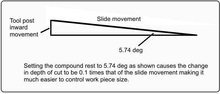
    The sketch below shows why I use this angle;
    Attachment 16293

    We can see that with that angle the inward feed of the toolpost is 1/10 of the travel of the compound slide. We have therefore increased our setting accuracy by a factor of 10 compared to adjusting the tool post position with the cross slide dial. !0 thou on the compound slide is 1 thou infeed. Likewise 1 thou on the compound is a tenth infeed.

    Attachment 16294
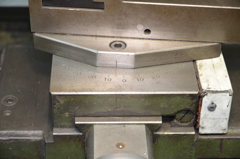
    Here is an real example.

    I mentioned in another post that I always like to do an error analysis when working with numbers, so how critical is the calculated angle. Roughly the error in infeed is approximately 4 to 5% for 1/4 deg error in setting. That sounds a lot but let's put it in perspective in comparison to using the cross slide.
    Say we set the compound at 5.5 deg instead of the target 5.74 deg then if we move the compound by 10 thou aiming for 0.001" at the work piece we will only get 0.000958" or less than 1/2 a tenth error. Try that with the dial on the cross slide. In any case if you can't set the compound angle any better than that you probably couldn't set the infeed any better than 1/4 thou on the cross slide.

    I have been careful to talk about tool post movement or infeed and not actual metal removal. When using a lathe tool, advancing the infeed by 1/10 thou with usually not remove 1/10 off the radius, often it will just rub on the surface. Tool sharpness and material properties have important influences on this and is beyond the scope of this post. However, if you are using a tool post grinder then a 1/10 infeed might actually take 1/10 off, when using a fresh wheel.

    A side advantage, though often an important one, is that a small angle on the compound rest gives more clearance when you are working close to the tail stock. Many lathes with the compound at 0 deg. restrict the infeed position of the cross slide.

    Attachment 16295 Attachment 16296
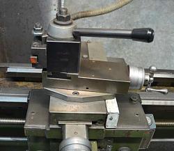
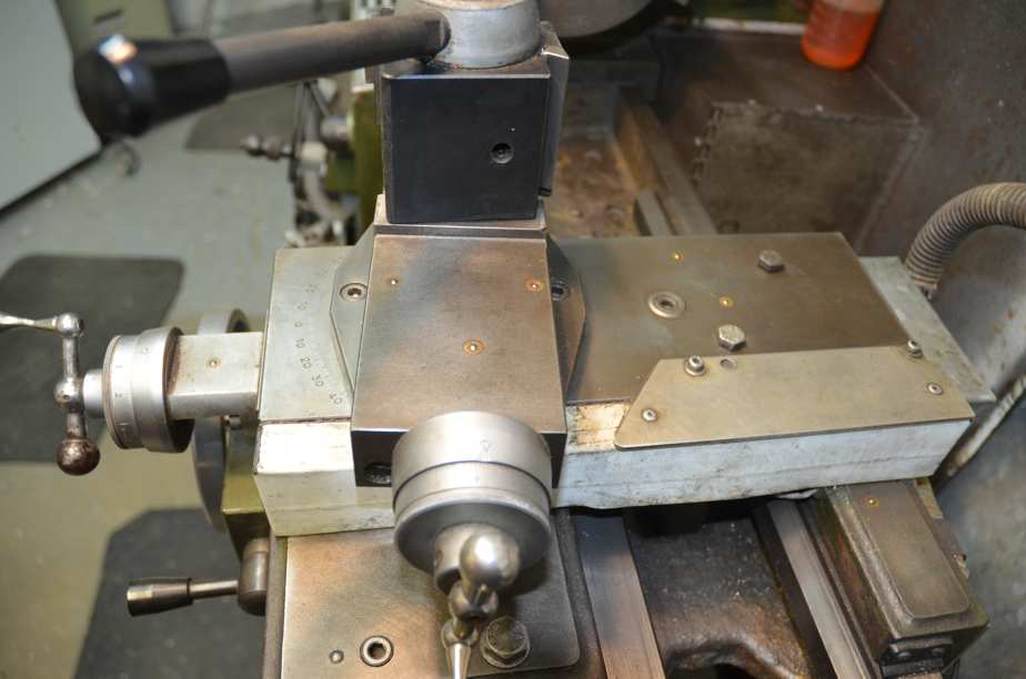
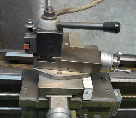
    Two views of the offset compound rest close to 5.74 deg.

    Thanks for watching.
    Been using this method since finding out about it when i first got me lathe.This tool combined with 1 in 10 set over is invaluable for taking off those pesky tenths and also leave a fine finish on ordinary non free machining mild steel.This one has had much use and sharpening so needs a regrind to regain a bit more hook.Tool is lightly clamped straight into toolpost dead square to work andthe straight cutting edge is set at any angle 45-85 to vertical and swarf comes off like the finest of cobwebs
    Attached Thumbnails Attached Thumbnails Improving lathe turning accuracy.-20180928_111348-001.jpg  

  5. #14
    Supporting Member tonyfoale's Avatar
    Join Date
    Nov 2016
    Location
    Spain
    Posts
    1,561
    Thanks
    687
    Thanked 2,646 Times in 709 Posts

    tonyfoale's Tools
    Quote Originally Posted by Daturat100r View Post
    Been using this method since finding out about it when i first got me lathe.This tool combined with 1 in 10 set over is invaluable for taking off those pesky tenths and also leave a fine finish on ordinary non free machining mild steel.This one has had much use and sharpening so needs a regrind to regain a bit more hook.Tool is lightly clamped straight into toolpost dead square to work andthe straight cutting edge is set at any angle 45-85 to vertical and swarf comes off like the finest of cobwebs
    You might also like this post. http://www.homemadetools.net/forum/s...9276#post88966


    186 More Best Homemade Tools eBook

  6. The Following User Says Thank You to tonyfoale For This Useful Post:

    Daturat100r (Sep 28, 2018)

Thread Information

Users Browsing this Thread

There are currently 1 users browsing this thread. (0 members and 1 guests)

Tags for this Thread

Bookmarks

Posting Permissions

  • You may not post new threads
  • You may not post replies
  • You may not post attachments
  • You may not edit your posts
  •