
 LinkBack URL
 About LinkBacks

I recently purchased a 3" Precision Milling Vise from LMS. (No affiliation, just a customer.) This vise is a "Kurt-style" vise with a removable swivel base. Like a lot of Chinese manufactured items, there were quality control and other small issues.
I identified three areas where I felt the need to work on this vise to better suit my application. Here is a summary followed by the details and pictures.
First, the quality of the cast vise wrench is poor, and it did not fit the hex on the vise screw well at all. To their credit, LMS is arranging a replacement wrench for me. I decided to modify the original anyway.
Second, the vise comes with a pair of alignment blocks to easily align the vise (or the swivel base) with the T-slots in the mill table. The blocks provided, along with the machined mounting grooves on the bottoms, are for T-slots that are 14mm wide. The T-slots on my milling table are 12mm wide.
Third, I previously made a set of adjustable vise stops (https://www.homemadetools.net/homema...le-vise-stop-3) for my screwless vise and wanted to be able to use these with the new vise. I decided to make an adapter that can be easily attached without modifying the vise.
------------
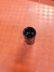
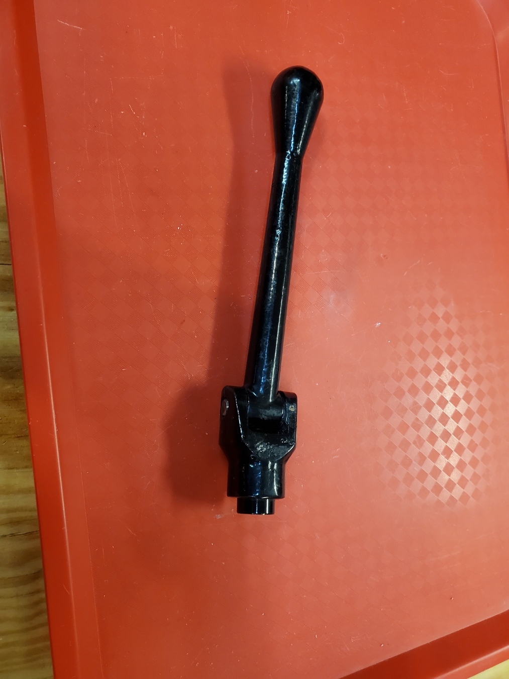
The Wrench
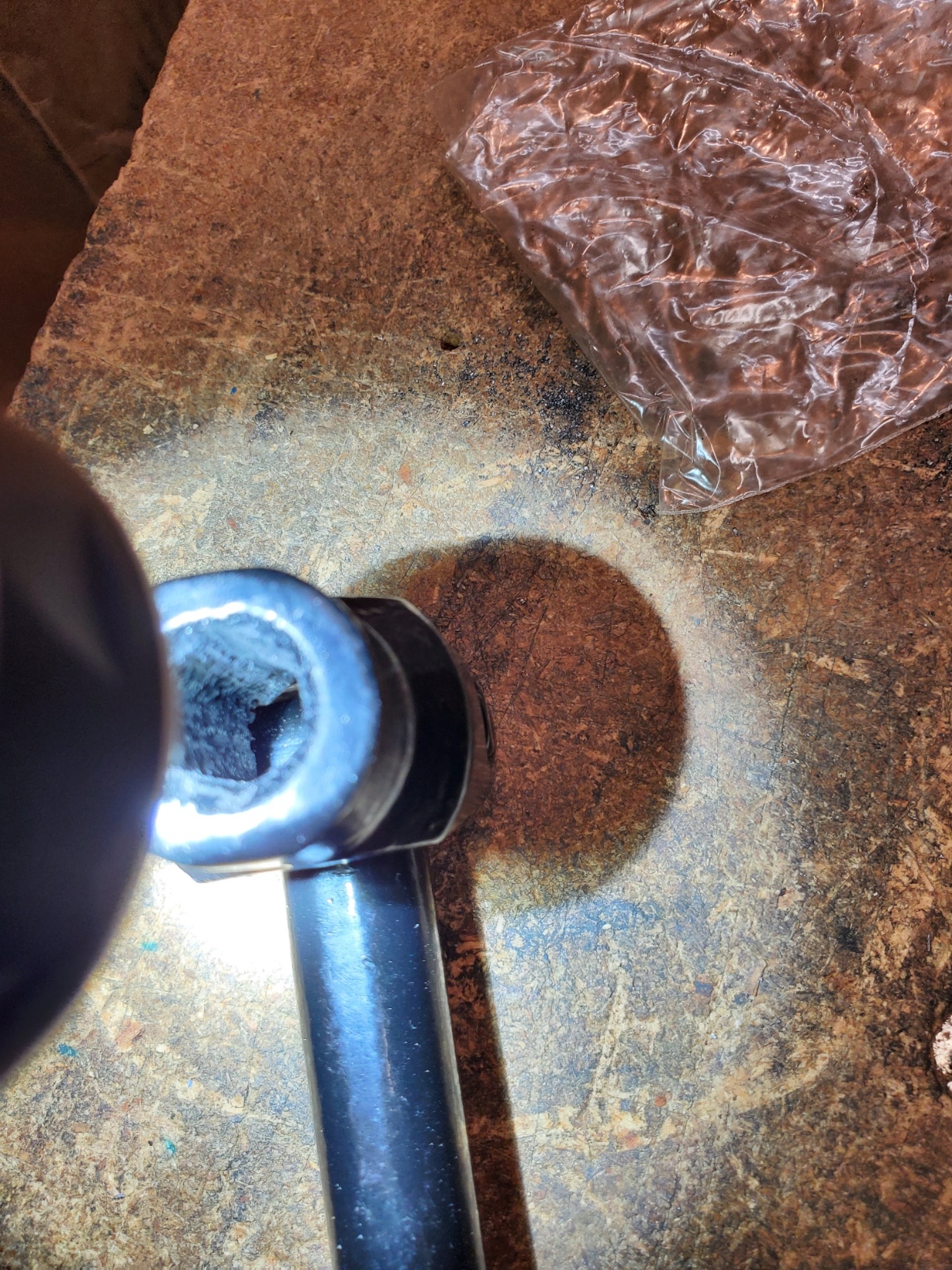
This is a picture of the inside of the "socket" end of the wrench. This picture taken after I used a hand file to open it up to better fit the hex on the screw. It still did not fit well.
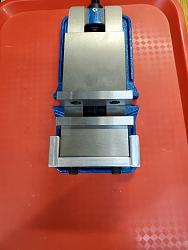
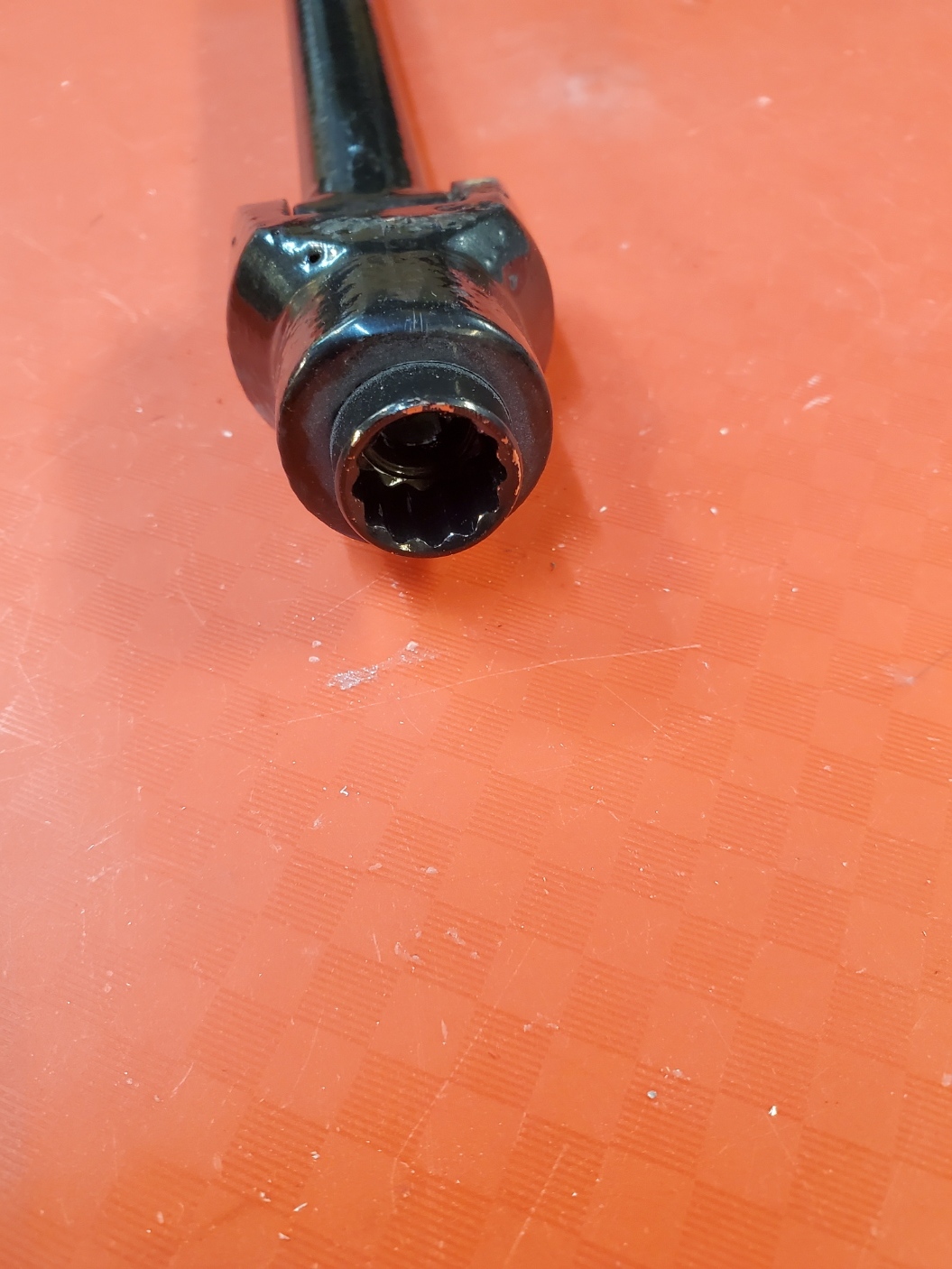
I have an inexpensive set of HF sockets, so I selected the correct size and mounted it in the handle. I disassembled the handle and mounted the end in the vise on my mini mill. I milled and then bored out a gentle press fit for the socket. I did not want to make it a tight press fit for fear of cracking the casting. I pressed it in and then reassembled the handle.

Fits and works perfectly. If the socket comes loose in the future, I'll drill a cross-hole and pin it in place.
------------
The Alignment Blocks
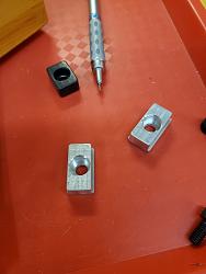
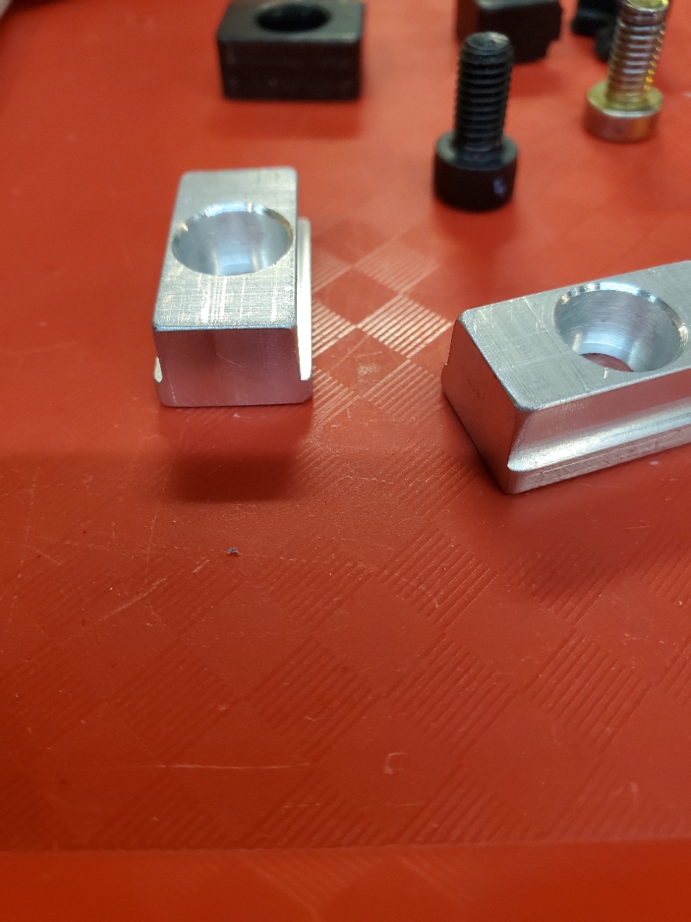
The alignment blocks and corresponding mounting grooves on the bottoms of the vise and base are 14mm wide. They are probably sized for a bench-top mill, rather than a mini-mill which has 12mm T-slots. I decided to make a pair of step-down blocks. They are 14mm wide where they fit the mounting groove, and 12mm wide where they fit into the T-slot on the mini-mill table. I made them from aluminum to prevent damage to the table.
Closeup pictures of the blocks. One of the original blocks (black) is in the background.
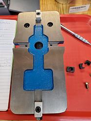
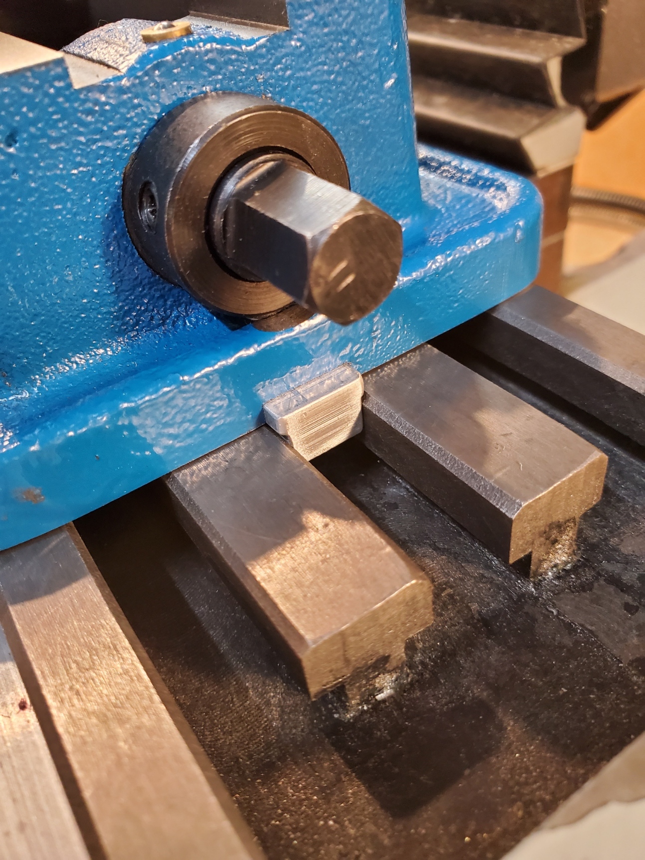
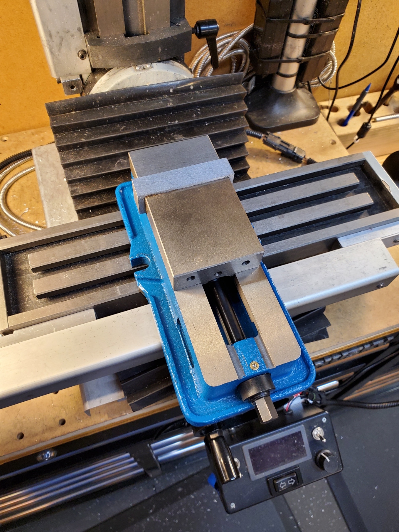
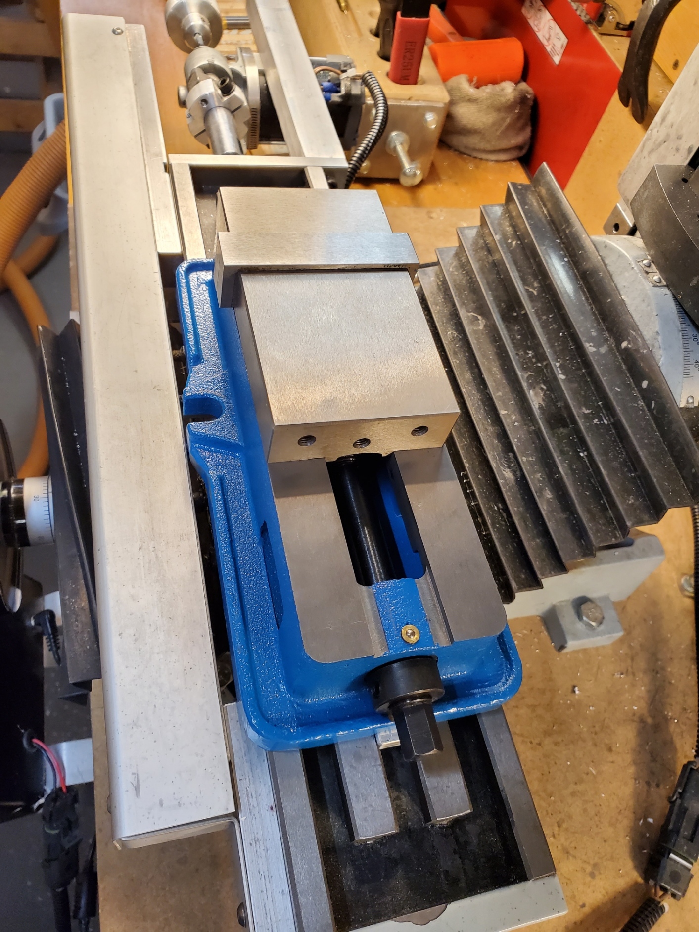
Pictures of the blocks installed on the bottom of the vise.
Pictures of the vise installed on the mill table.

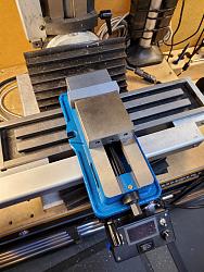
Not quite sure how to secure the vise to the table when oriented as in the last picture. The mounting slots in the base of the vise are too wide to use the table T-slots. I could use regular T-slot clamps on the ends of the base of the vise... Any other suggestions?
------------
Adjustable Vise Stops
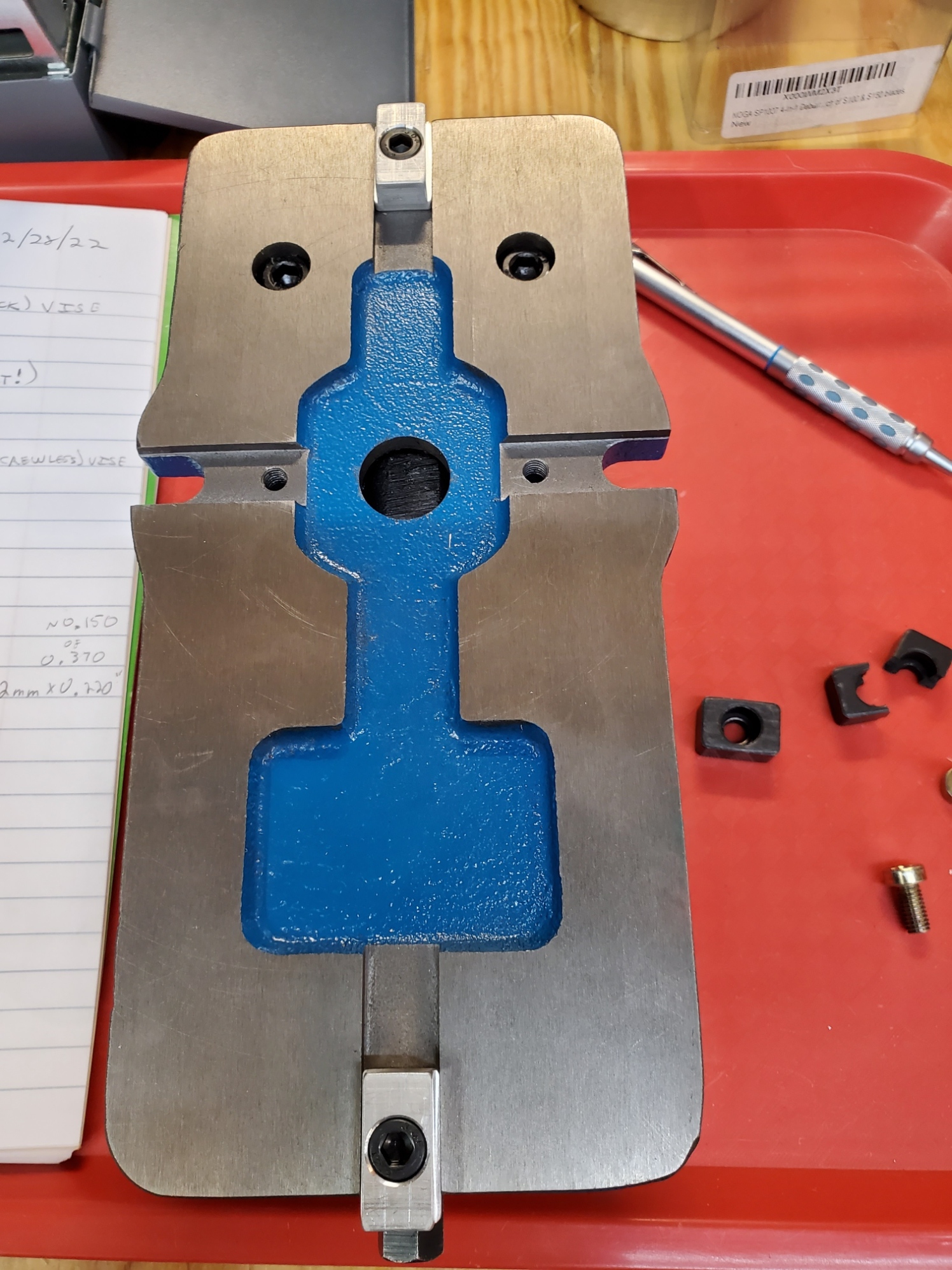
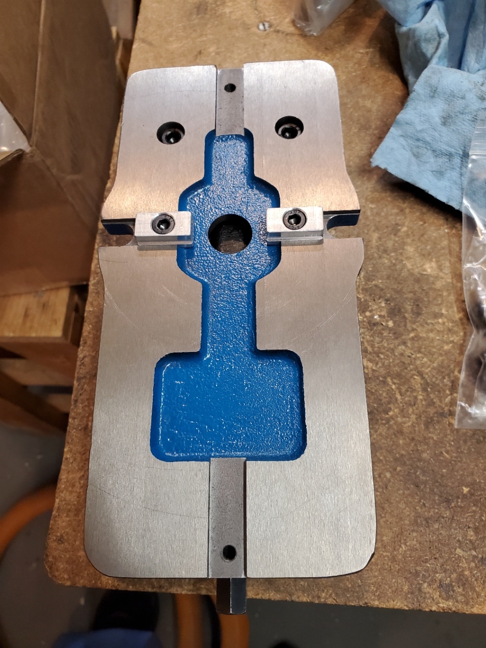
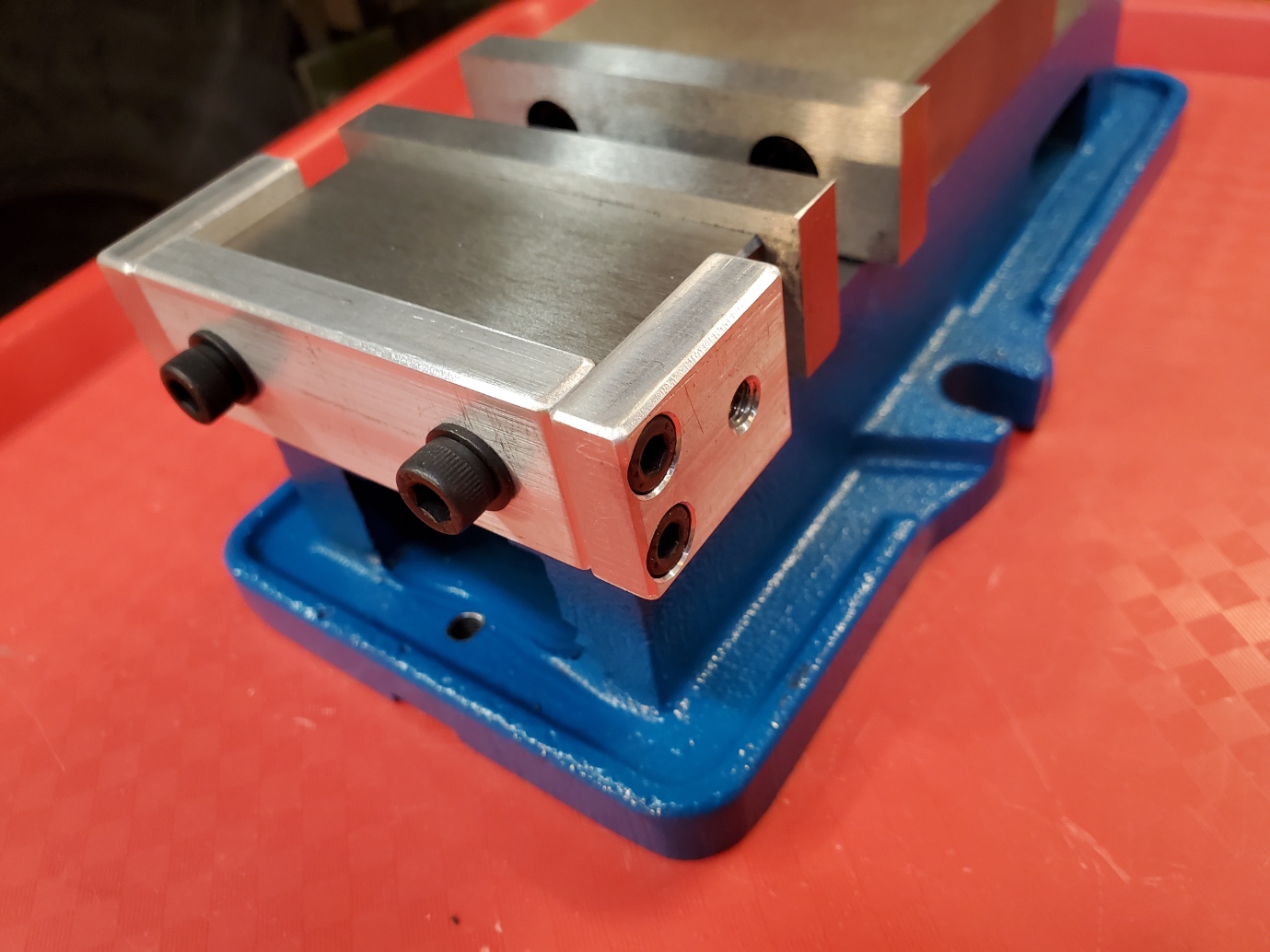
Here are a couple pictures of the Adjustable Vise Stop Adapter. It is mounted to the vise using the alternate mounting holes for the fixed jaw. It provides threaded holes in approximately the same locations as the mounting holes on my sides of my screwless vise.


 Reply With Quote

Bookmarks