
 LinkBack URL
 About LinkBacks

I needed stock depth stop capability for my mini lathe. I designed and built both an internal and an external stop. (I'll do a write-up the external stop at a later time.) The internal stop is secured in the end of lathe spindle, and has a rod that can be set to almost any depth inside the spindle or chuck.
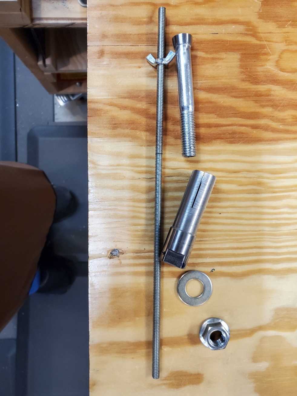
This picture shows all the various pieces.
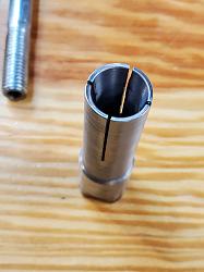
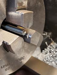
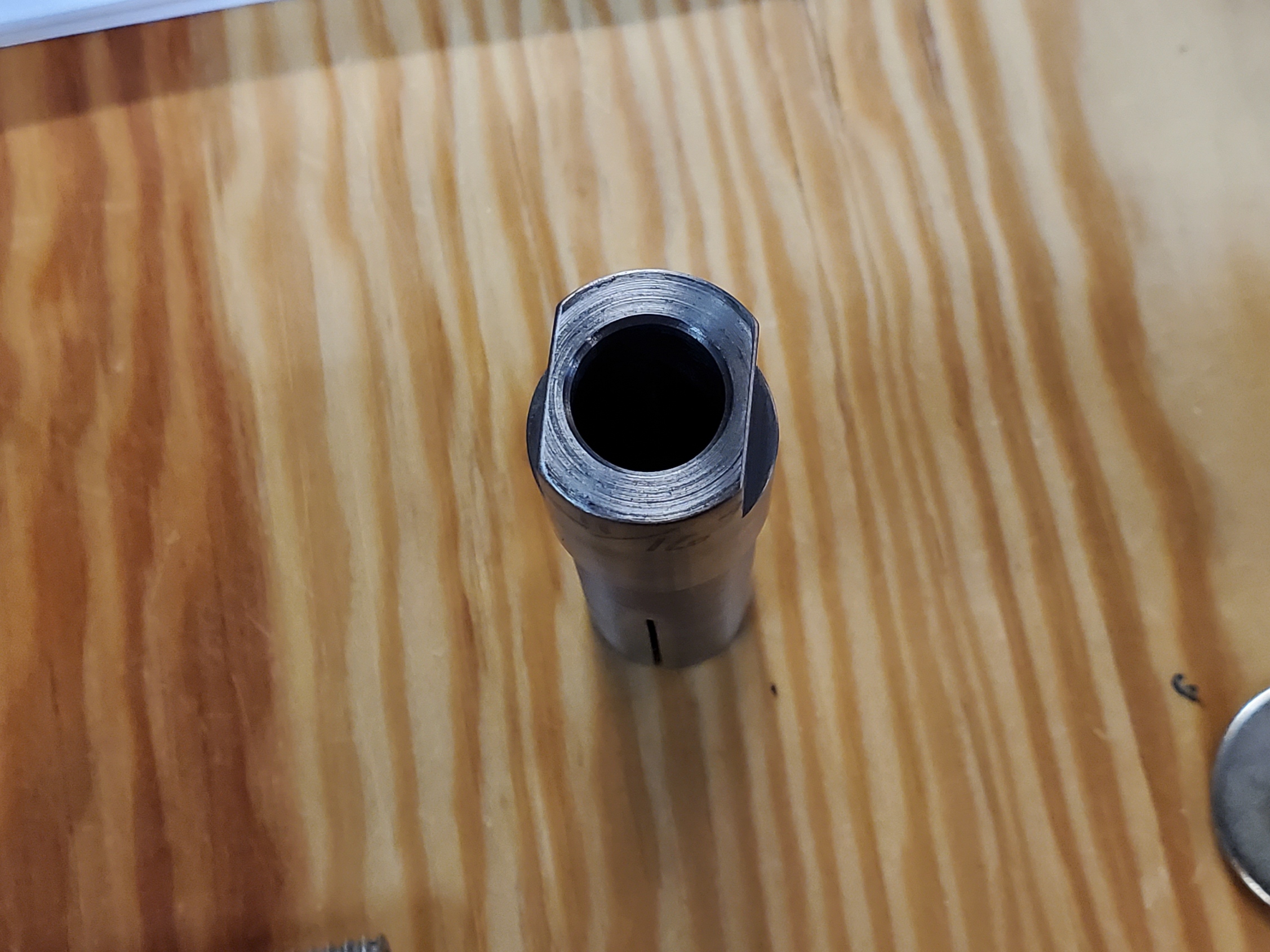
The sleeve is made from steel round bar. It is secured by a tapered bar drawn into the matching taper inside one end of the sleeve. The small diameter of the sleeve is turned to be a good slip fit in the spindle. The larger diameter fits through the hole in the change gear cover with a shoulder that rests on the end of the spindle. The expansion slits were cut on the mini mill using a thin slitting saw. I machined a pair of flats on the outer end of the sleeve so that a wrench can be used to hold it while the nut on the draw bar is tightened.
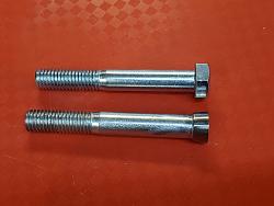
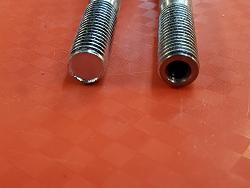
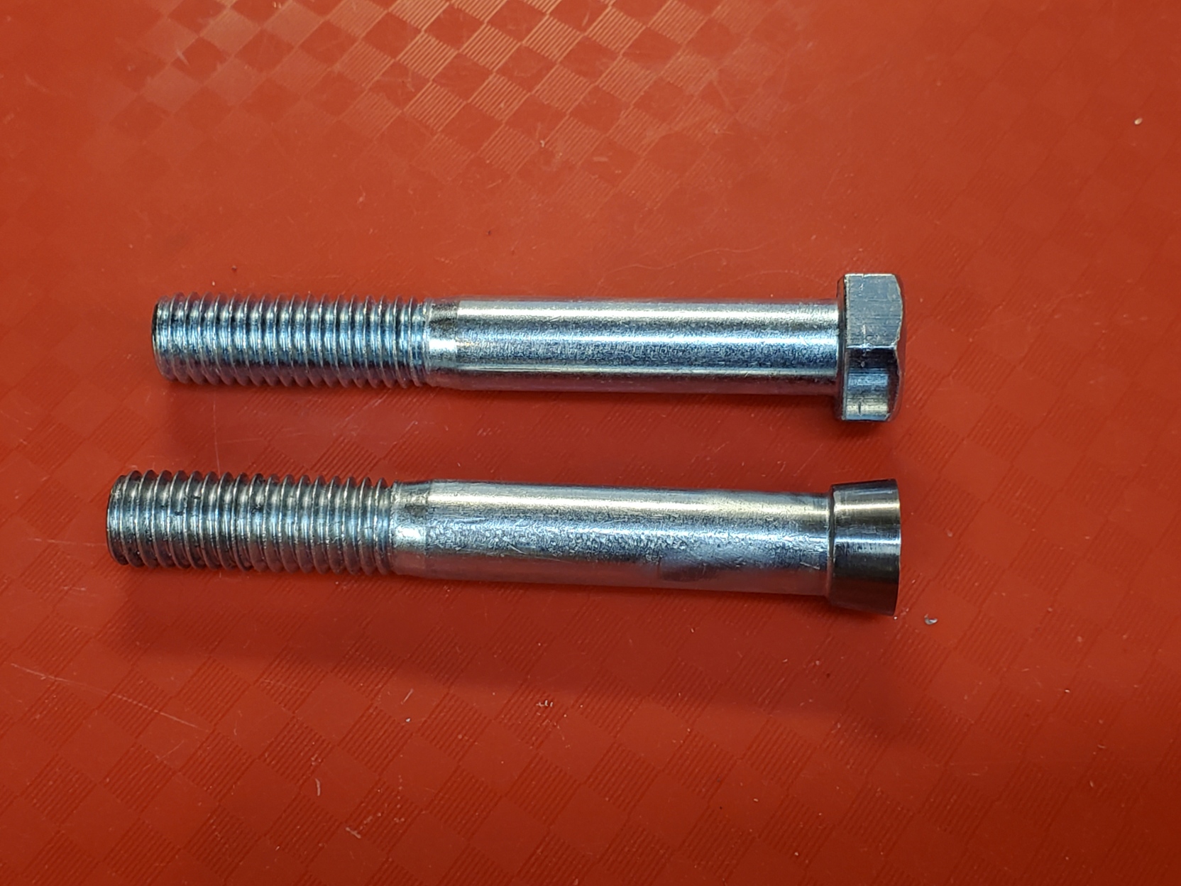
The draw bar is made from a common 3/8" bolt. I turned the head into a taper using the lathe. I drilled a 1/4" clearance hole most of the way through the bolt, and drilled and tapped about 1/2" in the threaded end to fit the 1/4-20 threaded rod used as the depth stop.
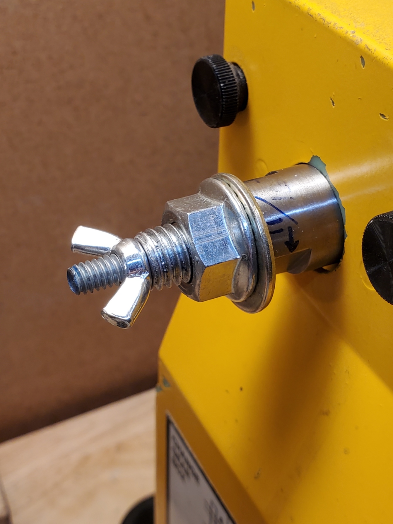
To install into the lathe... First the draw bar is inserted into the sleeve and held loosely by the washer and flanged nut. The sleeve is inserted into the spindle with the shoulder seated on the end of the spindle, and the nut is tightened to expand and secure the sleeve. Finally, a suitable length of threaded rod is threaded into the draw bar to set the depth, and a wing nut is used as a jam nut to secure the threaded rod position.
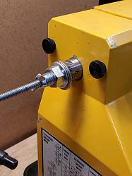
The stop is balanced well enough that it can be left in place while operating the lathe.
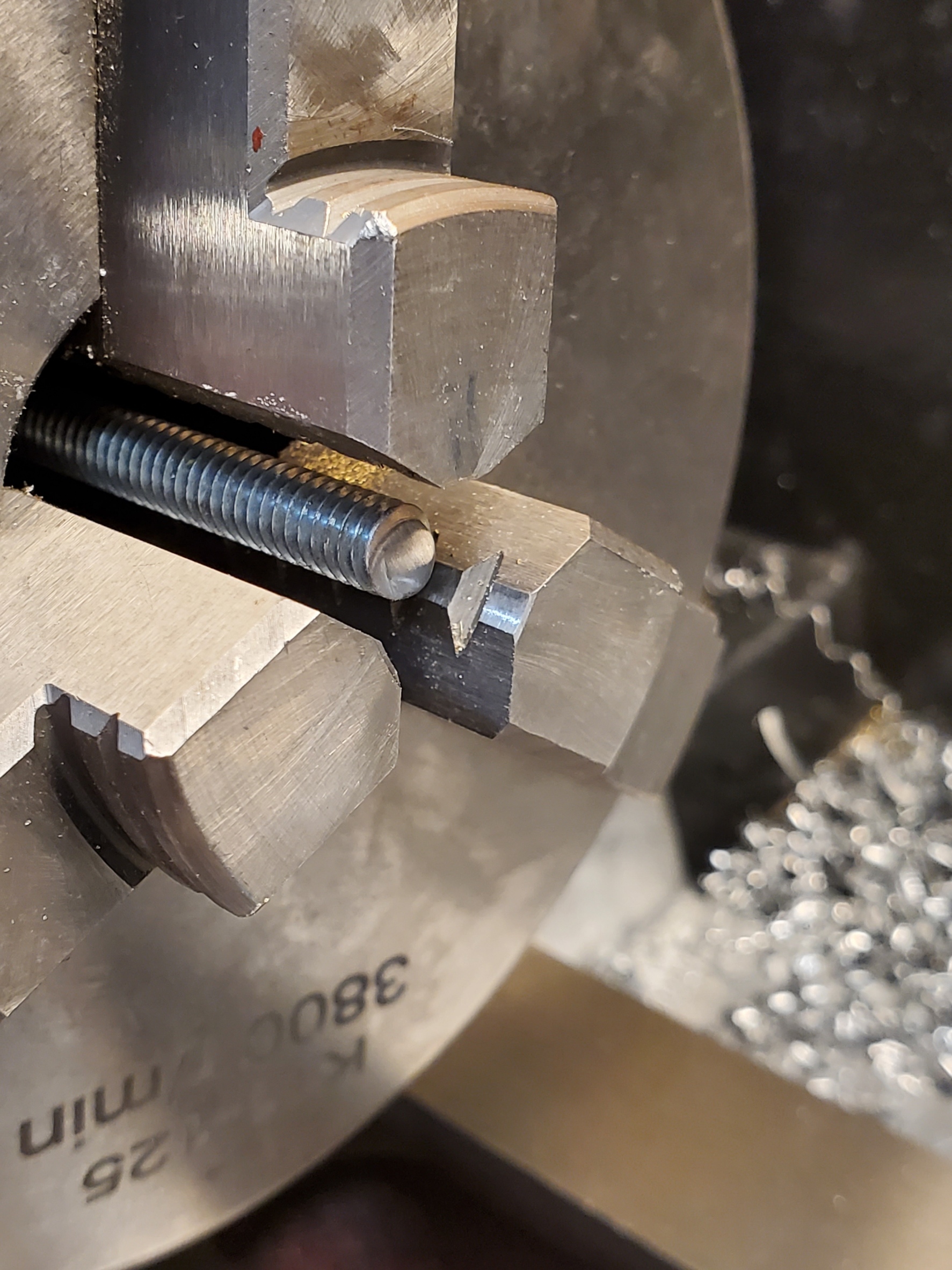
If a longer piece is being machined, a shorter length of threaded rod can be used so that the exposed portion doesn't whip around as the lathe runs.
Once set, the stop can be removed and reinstalled later using the shoulder to re-index the stop location. (This assumes that the nut torque is somewhat consistent between the repeated installations, and that the threaded rod is not disturbed, of course.)


 Reply With Quote

Bookmarks