
 LinkBack URL
 About LinkBacks


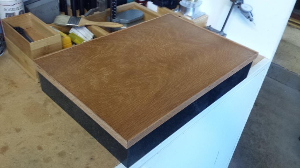
This easy to build surface plate cover is for a small 12” x 18” x3” granite surface plate. The cover adds protection to the top surface of the plate and can be used as a tray for small layout tools needed at the workbench. The custom milled red oak T-shaped edging is approximately 3/4” x 5/8” in cross section and the cover is 3/16” thick red oak plywood. DAP contact cement was used to glue the 1/2” wide center section of the edging to the plywood. This produces a very strong bond and does not require any fasteners. I applied several coats of clear polyurethane from a spray can to seal the wood and protect it from oil.
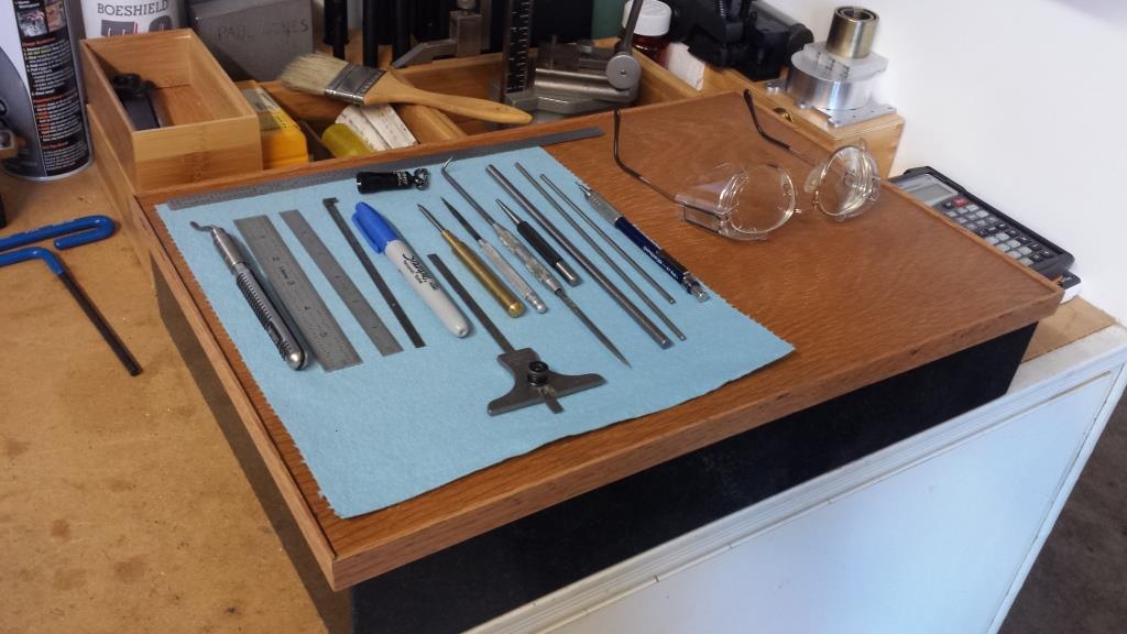
The completed surface plate cover and tool tray.
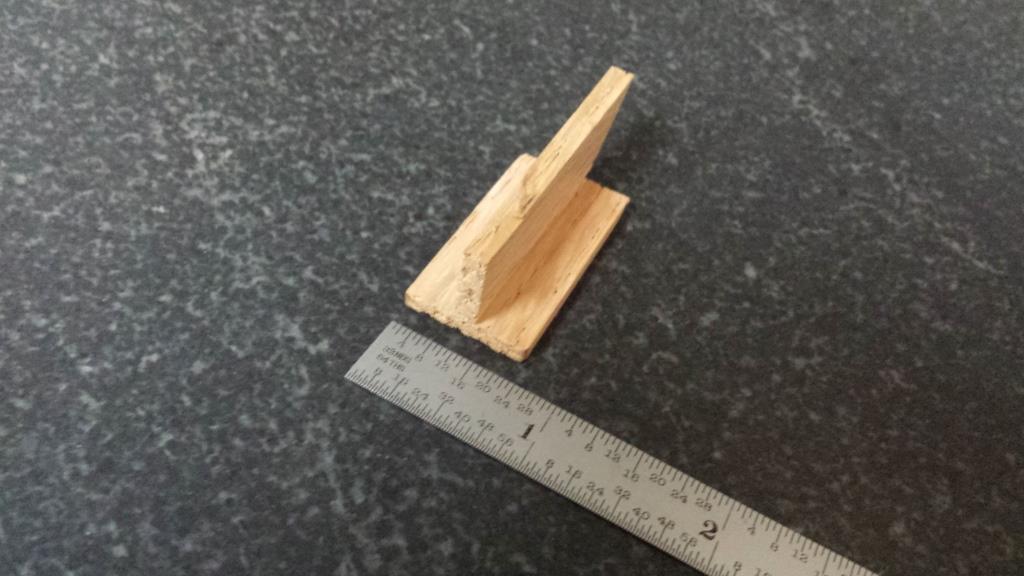
A view of the bottom section of the red oak edging after gluing with DAP contact cement to the 3/16”oak plywood. The lower skirt of the oak edging fits around the surface plate and holds it in place. Note the pencil line on the 45 degree cut. When fitting the fourth and final framing part cut with 45 degree corners, I always cut longer than marked and test fit which in this case allowed the part not to be cut too short.
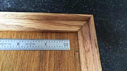
A cross section view of the oak edging.
Thank you for looking,
Paul


 Reply With Quote

Bookmarks