 LinkBack URL
 About LinkBacks
The software is in a previous comment.Originally Posted by bwhit5


The software is in a previous comment.

Ralphxyz (Jun 15, 2023)

I'm definitely interested in making either the tach or speedometer. Waiting for more

. "Pin It")
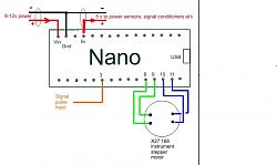
Just a quick one - your Nano schematic shows +5V power coming out to sensors etc from pin 28 - which is actually a Reset and 5V out is from the adjacent pin 27 (as actually indicated on your diagram - but not 'connected').
You spotted my deliberate mistake. I'll fix it and repost. Thanks for the heads up.
Sleykin (Jun 15, 2023)
Here's a quick one:
tonyfoale (Jun 15, 2023)


Impressive. Does it read electrical pulses from the ignition of does it read some kind of mechanical or magnetic input? I'm asking because I have a 1967 John Deer backhoe with no tach and, since it's a diesel, no electrical pulses to read. This maybe would fit the bill.
This explained in previous posts, particularly #15. I will be making another post soon discussing more detail on input options.
Sleykin (Jun 15, 2023)
The only post I see are yours and mine. Que pasa?

Count me in for those plans! The speedo in my '96 Mustang Cobra is flaky, so after I do a bunch of other work on it I'll tackle that.

Tony, did you post a link for the code? I have been trying to understand how to use a stepper for a indicator, with out any success.
Ralph
There are currently 1 users browsing this thread. (0 members and 1 guests)
 Posting Permissions

 Reply With Quote
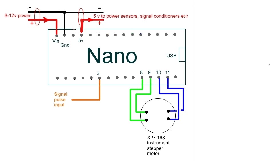
Bookmarks