Hi. Started work on a new project - Metal Shaper
Printable View
Hi. Started work on a new project - Metal Shaper
I'm really anxious to see this one completed because I want to build my own metal shaper too. I recently was able to score around 1000 lbs of scrap steel free so now I have the bulk of the material needed for it. I realized that I'll need a welder so first I'm going to have to build a TIG welder on a budget (I have a plan). I also bought an old used surface plate so now I have a way to make really flat surfaces and I'm gradually gearing up to start this project.
Keep on going man - your projects are often really inspiring.
Tuned in, ready and waiting, this is gonna be good :bananadance::D
Agreed this is going to be good . Maybe should have been in tools in progress though. so it doesn't get lost in the shuffle
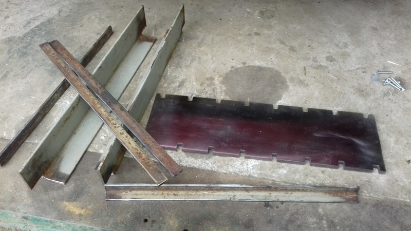
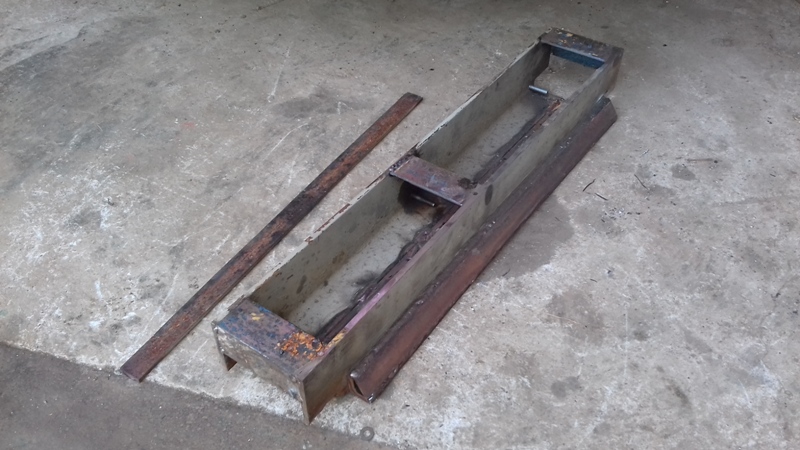
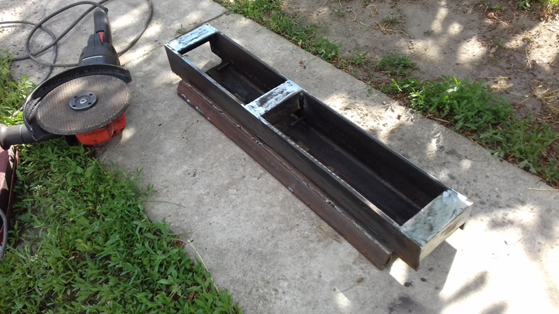
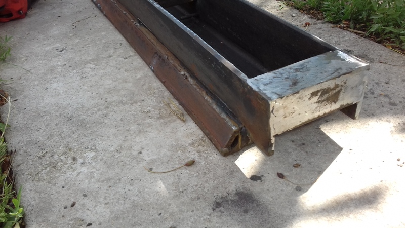
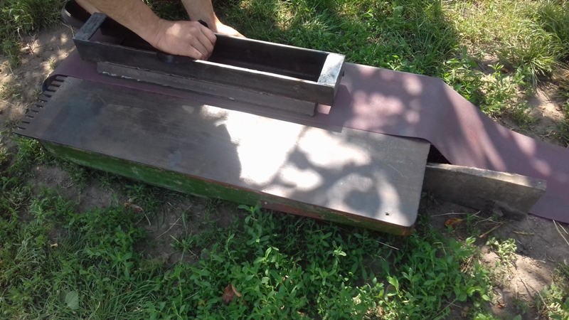
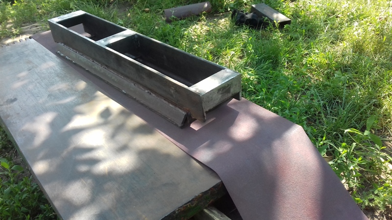
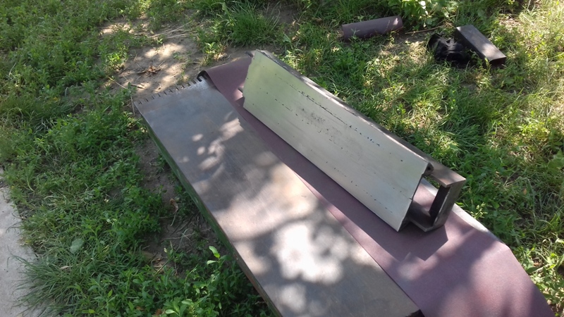
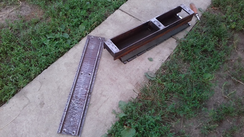
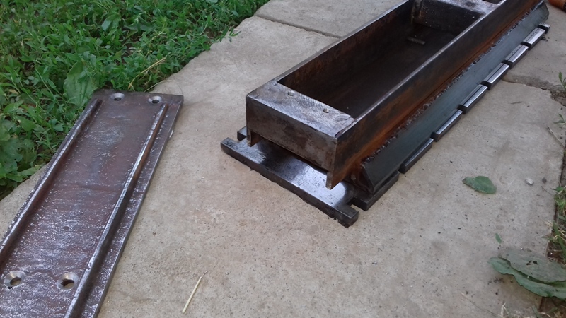
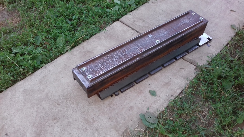
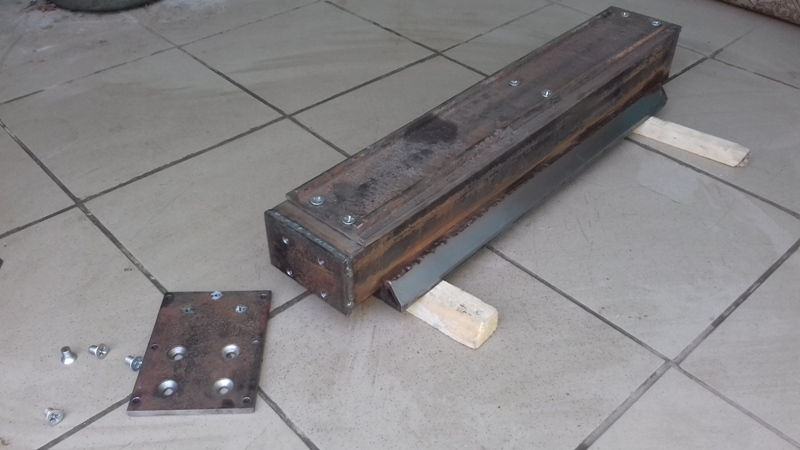
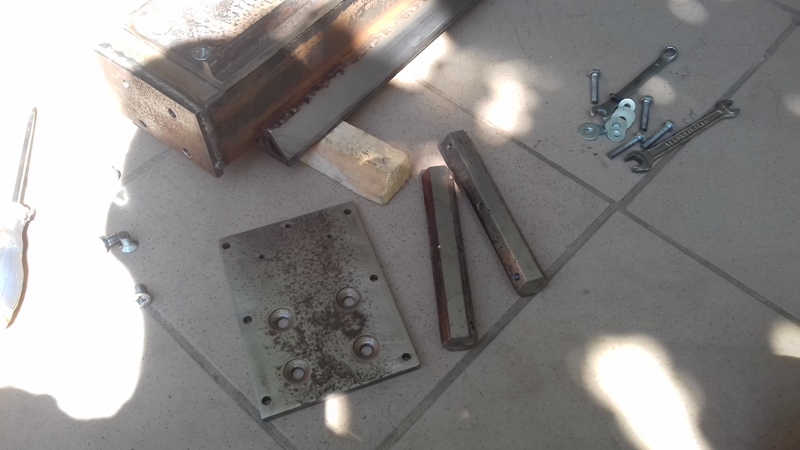
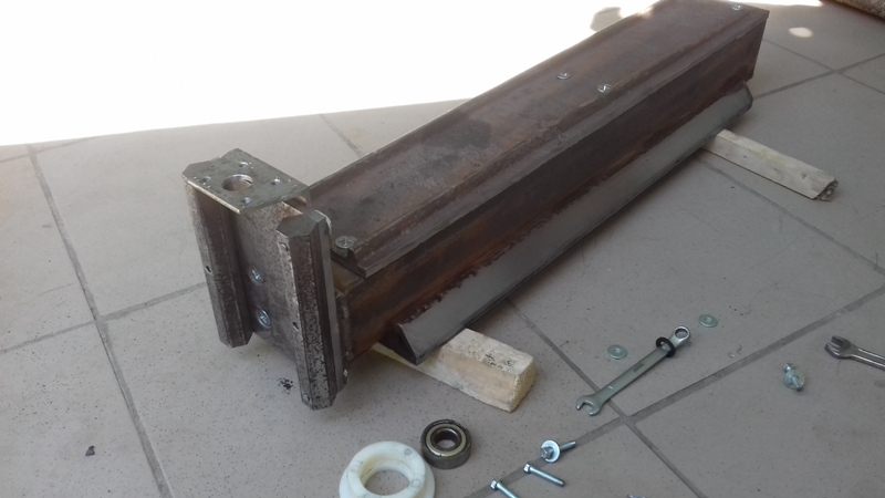
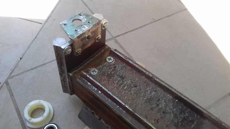
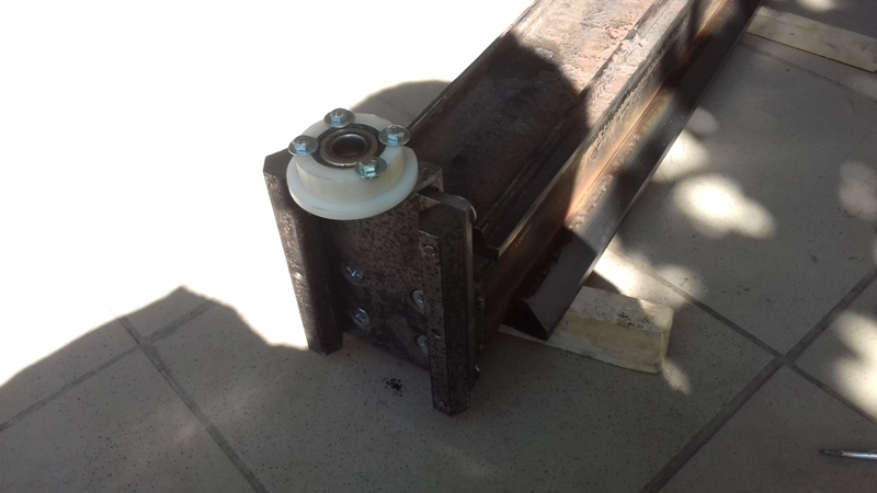
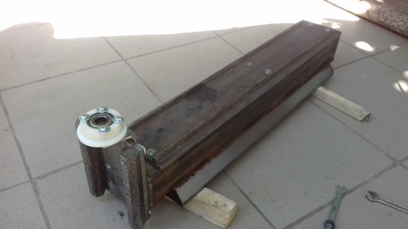
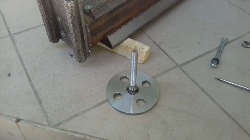
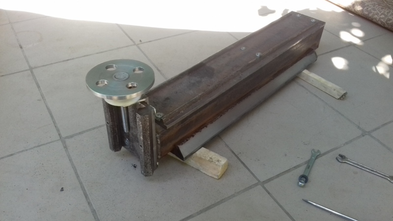
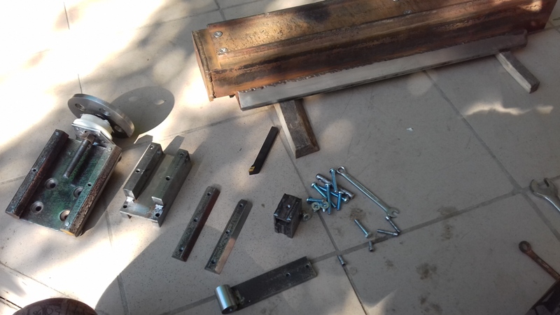
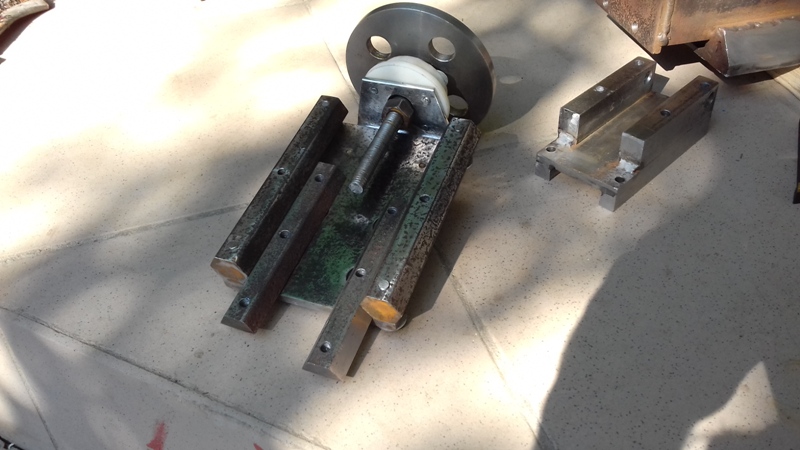
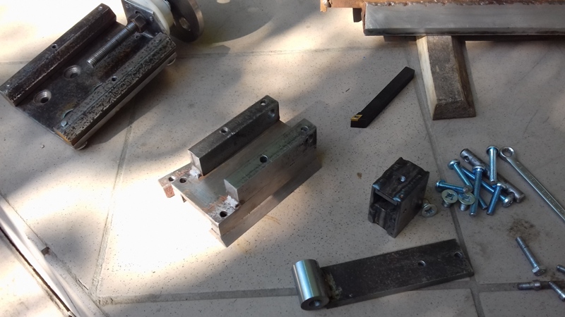
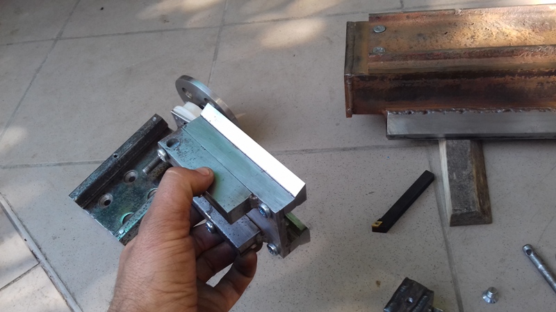
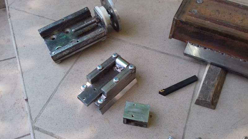
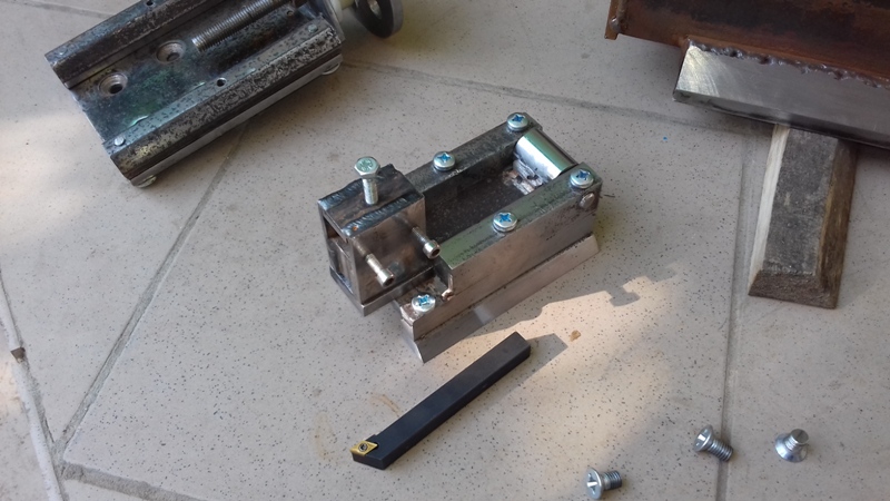
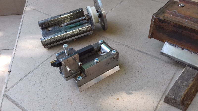
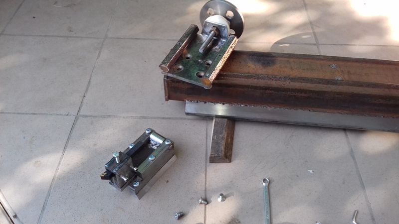
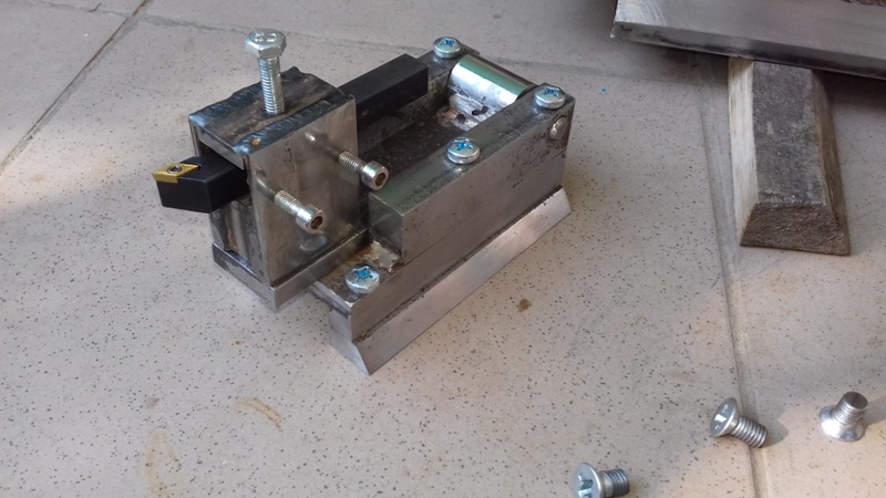
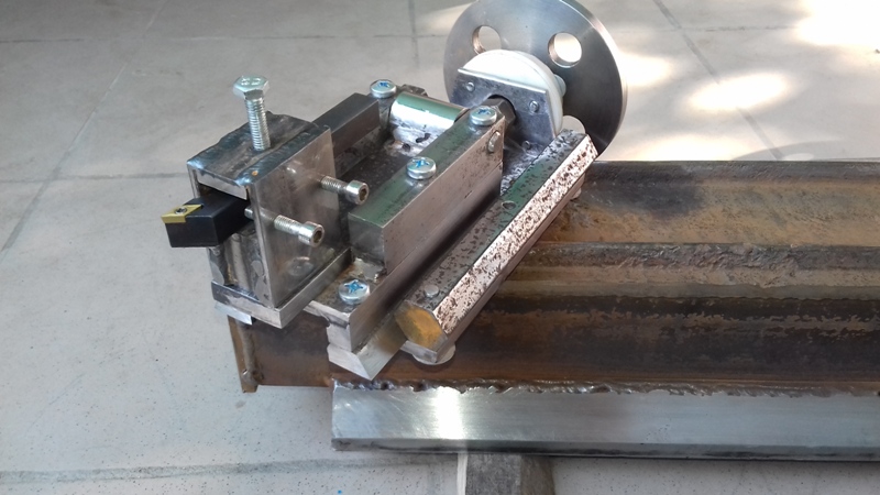
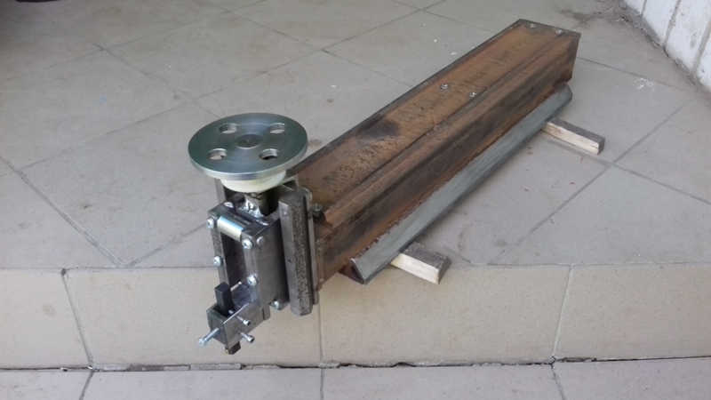
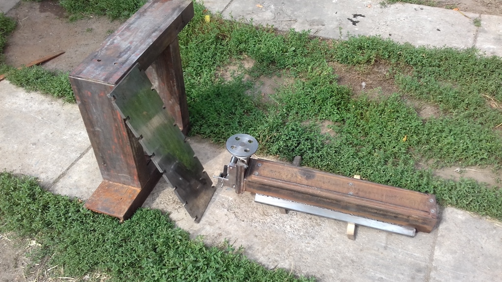
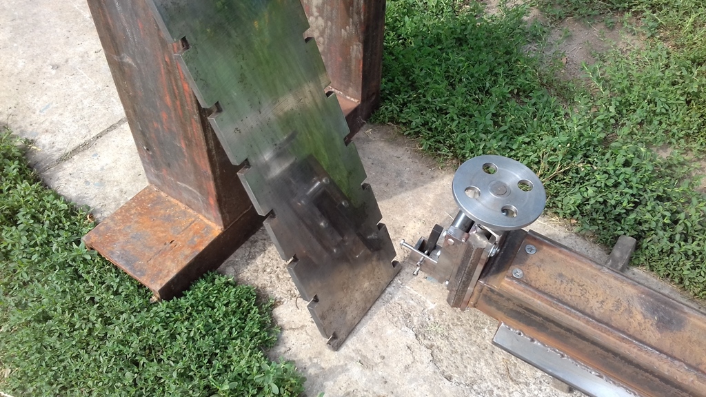
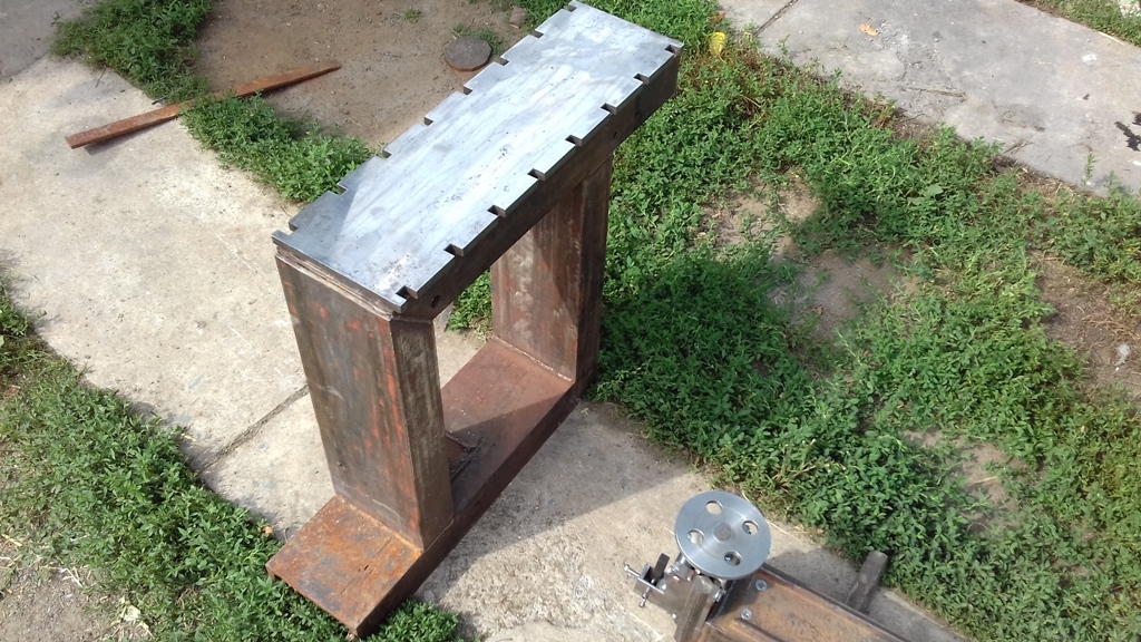
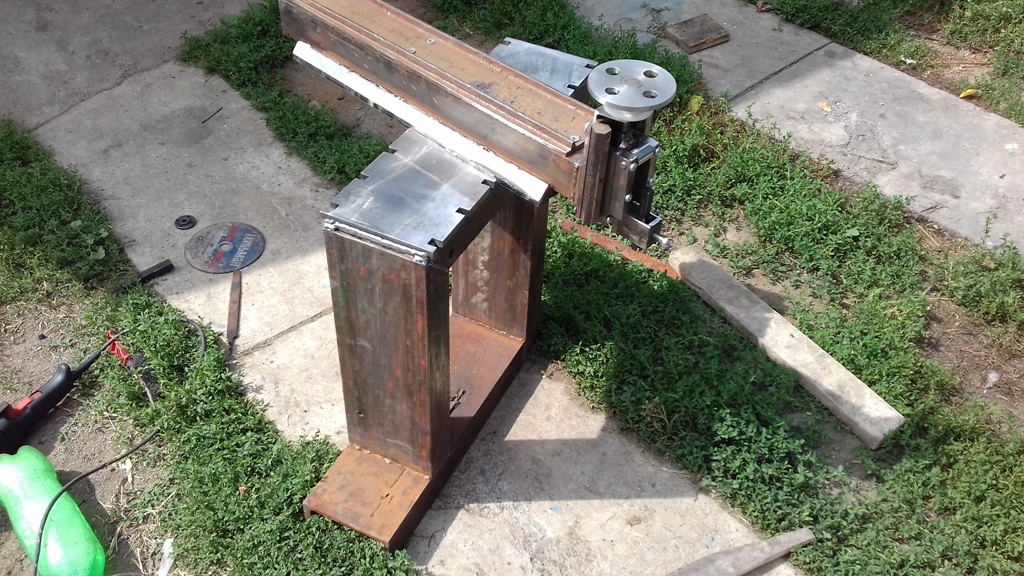
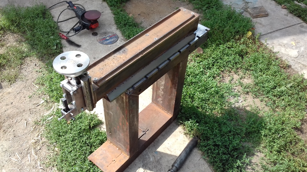
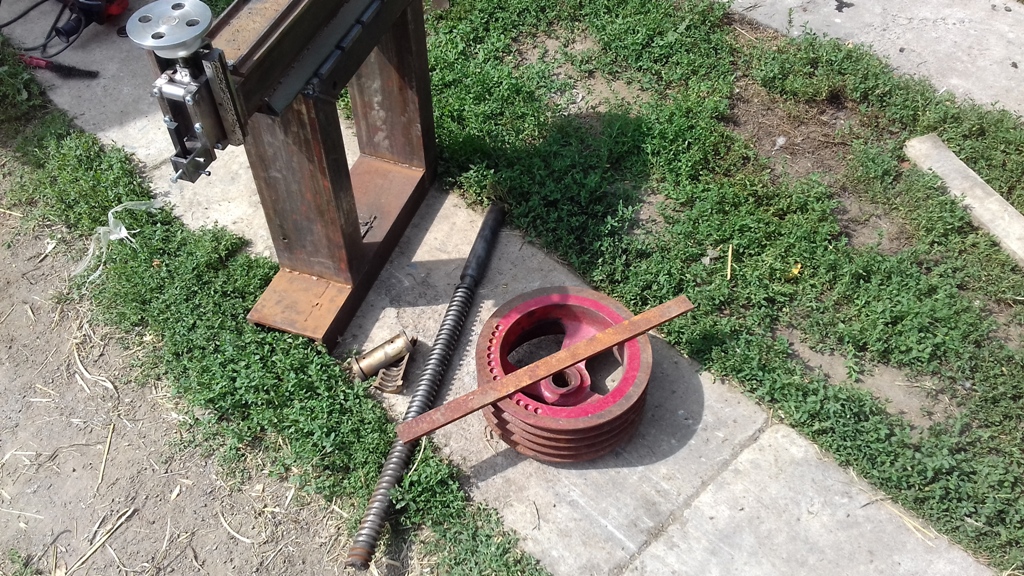
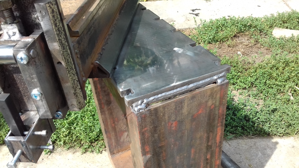
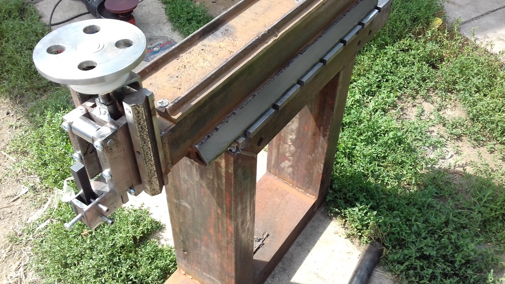
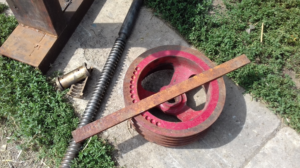
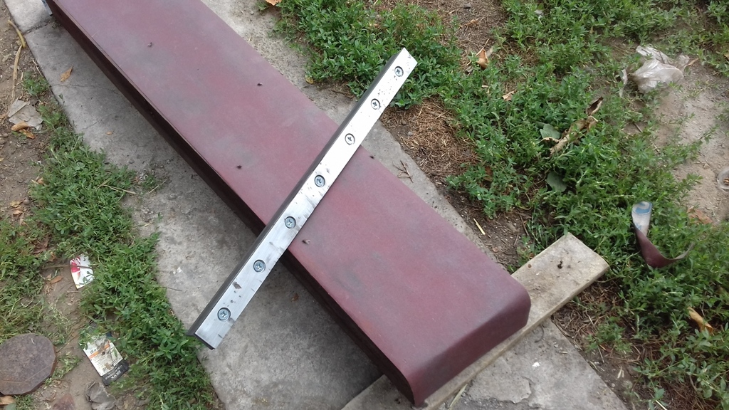
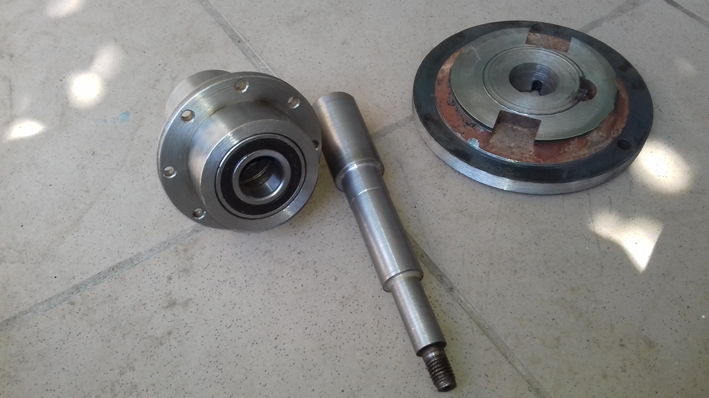
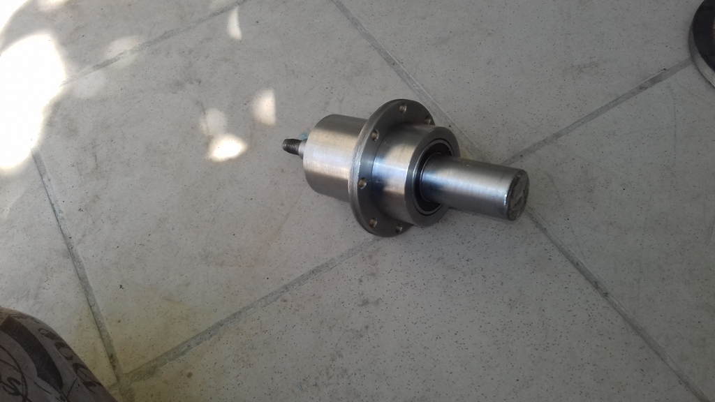
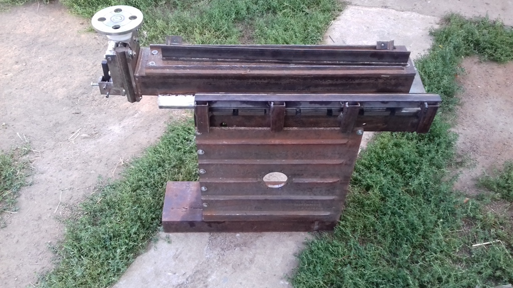
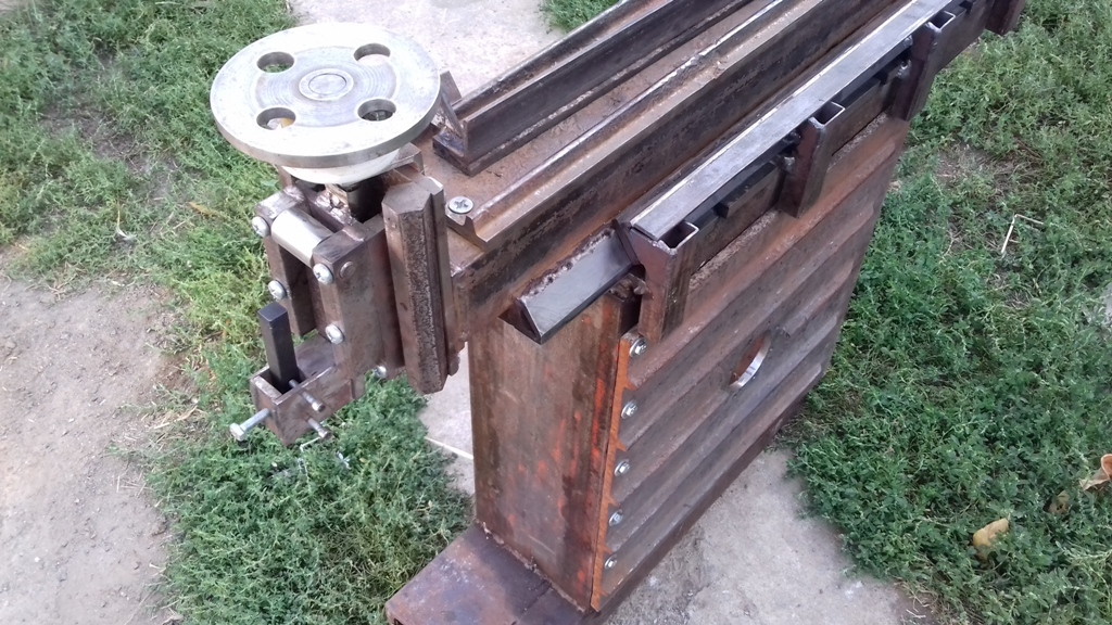
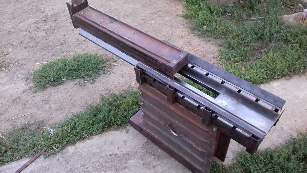
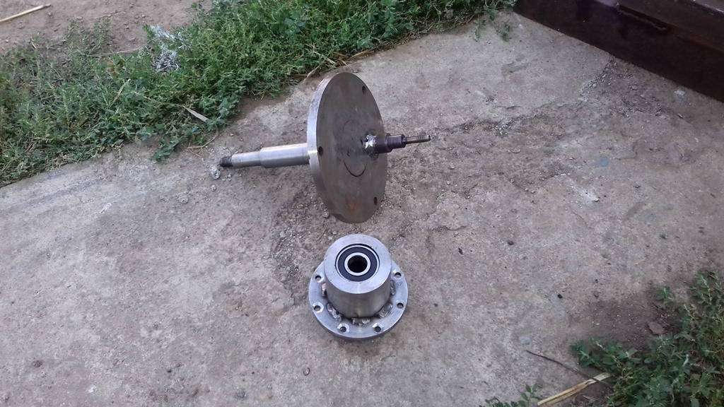
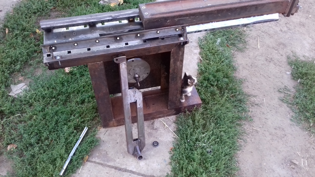
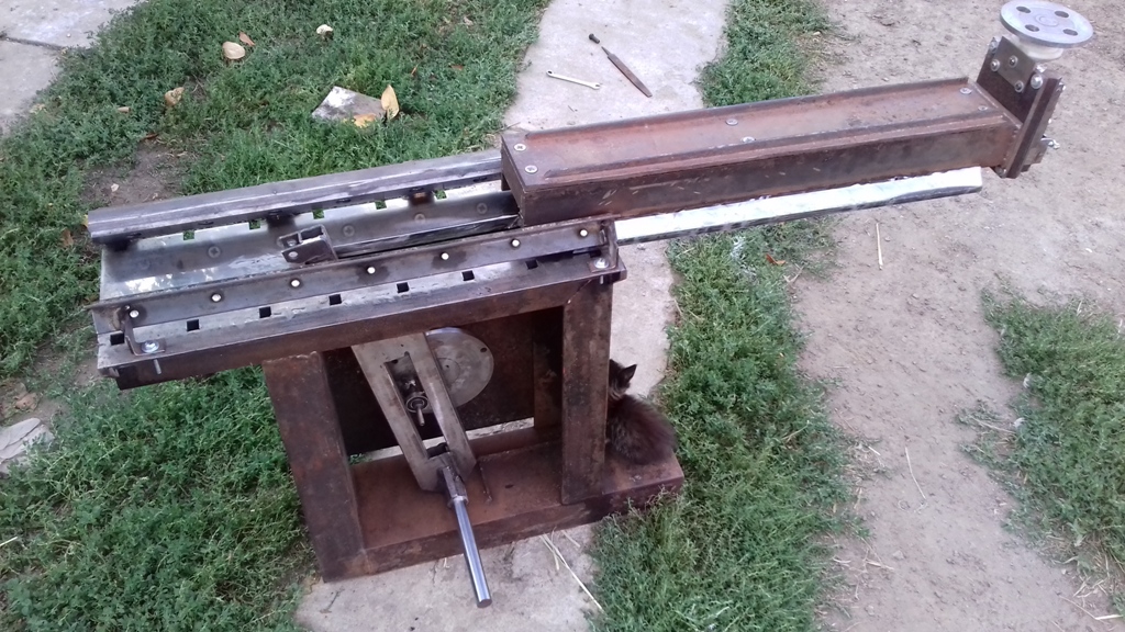
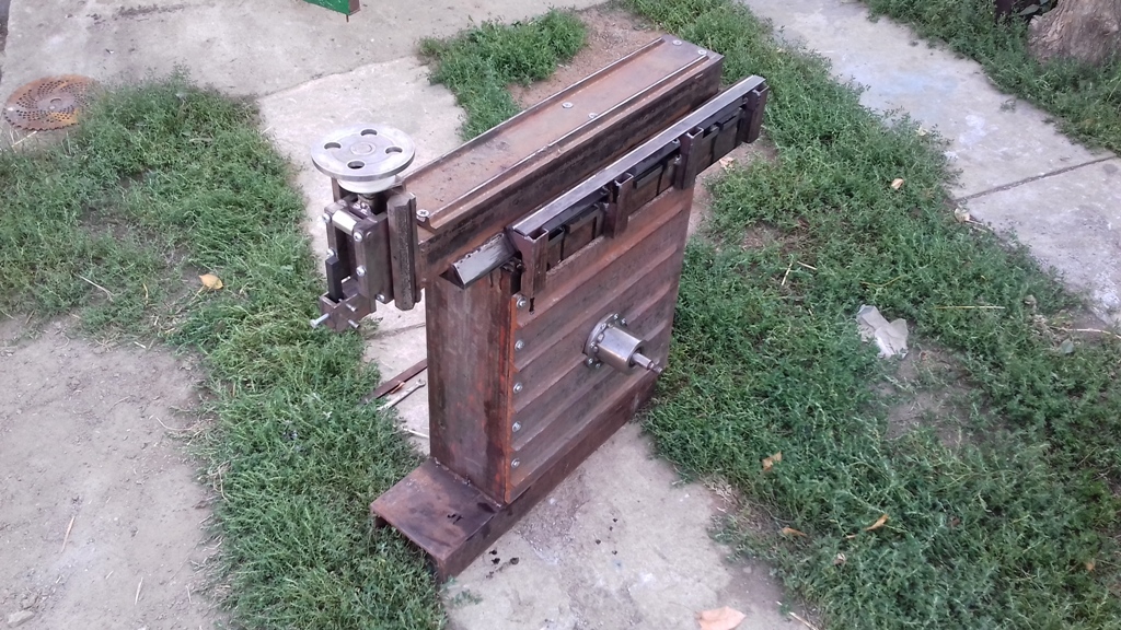
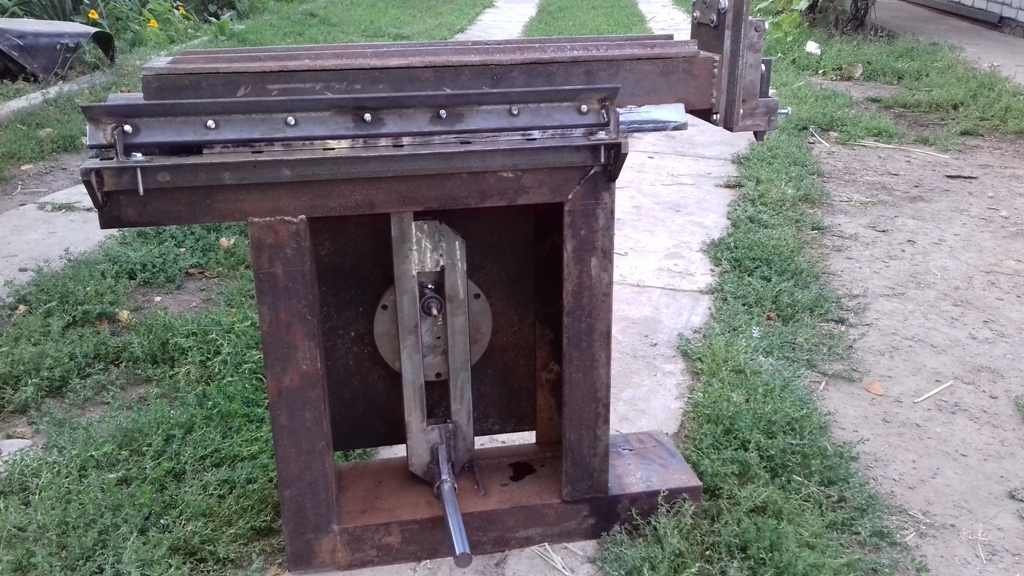
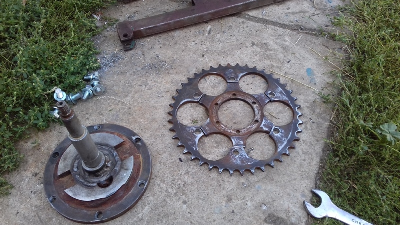
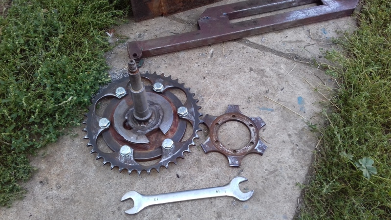
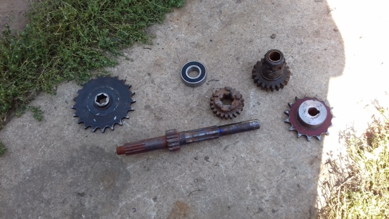
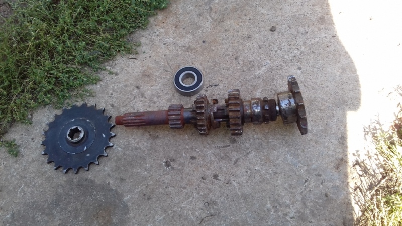
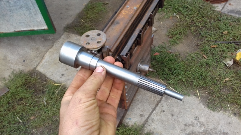
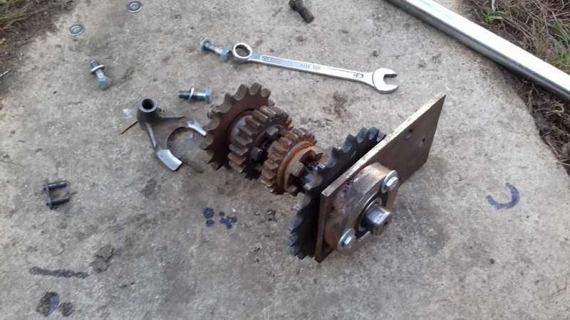
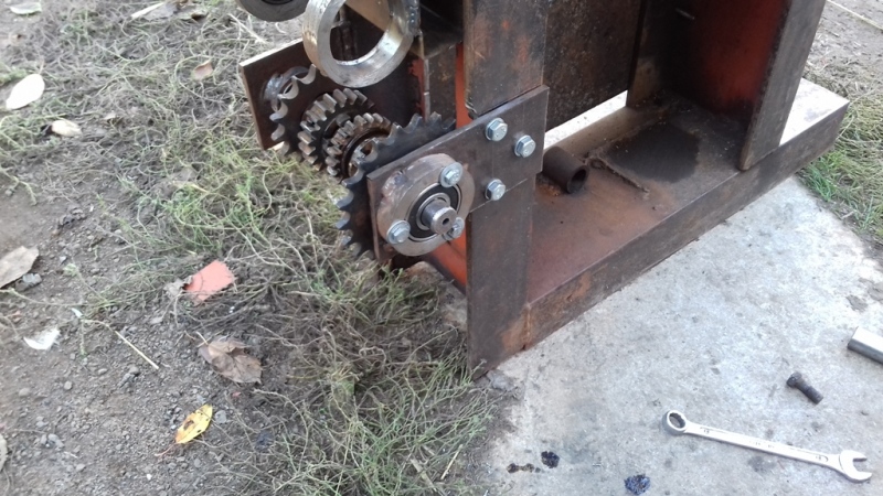
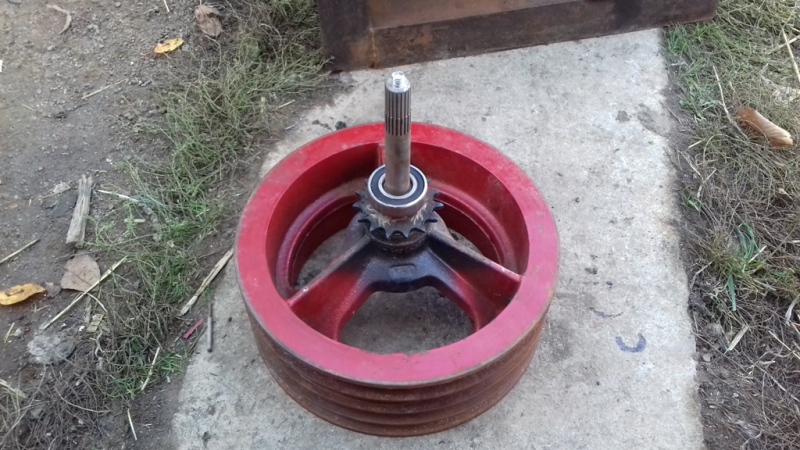
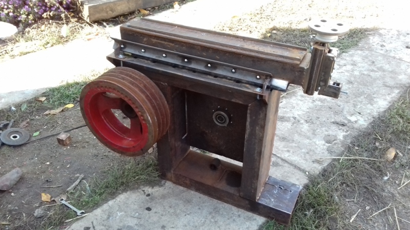
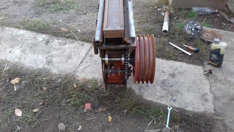
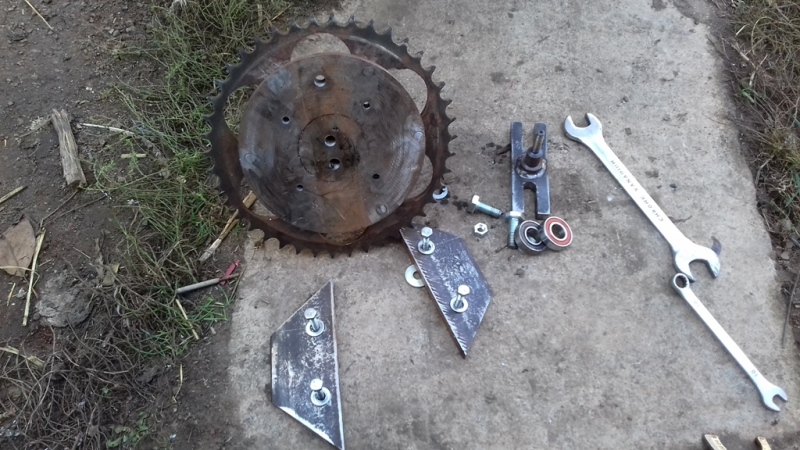
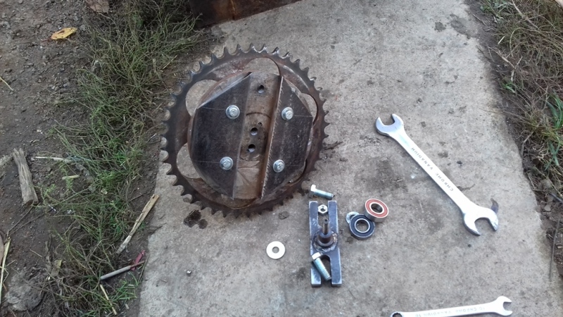
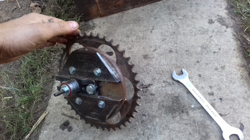
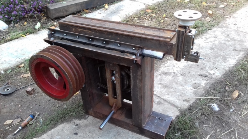
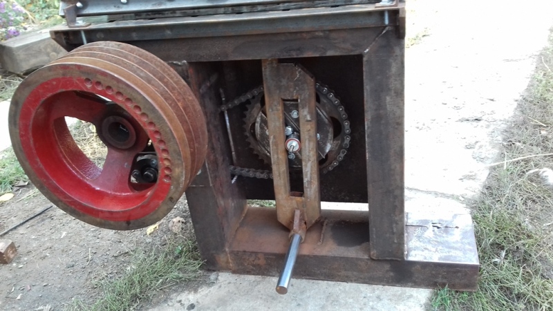
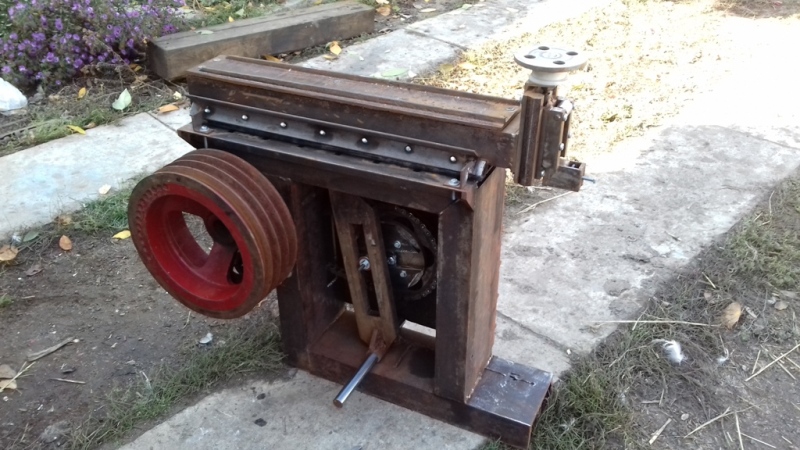
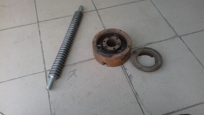
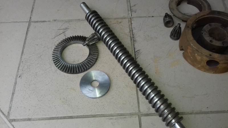
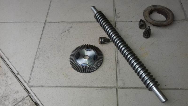
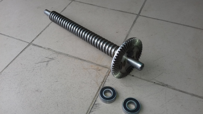
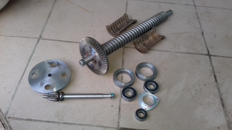
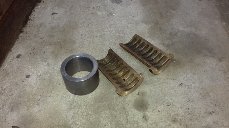
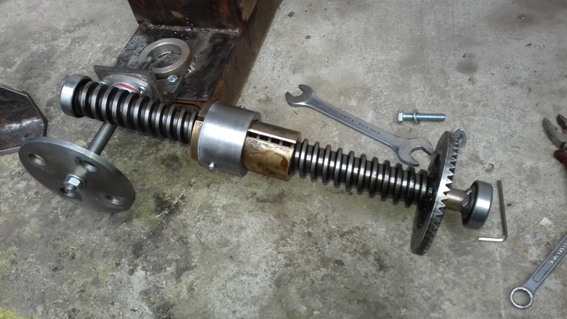
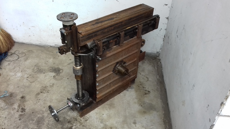
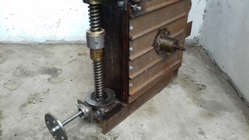
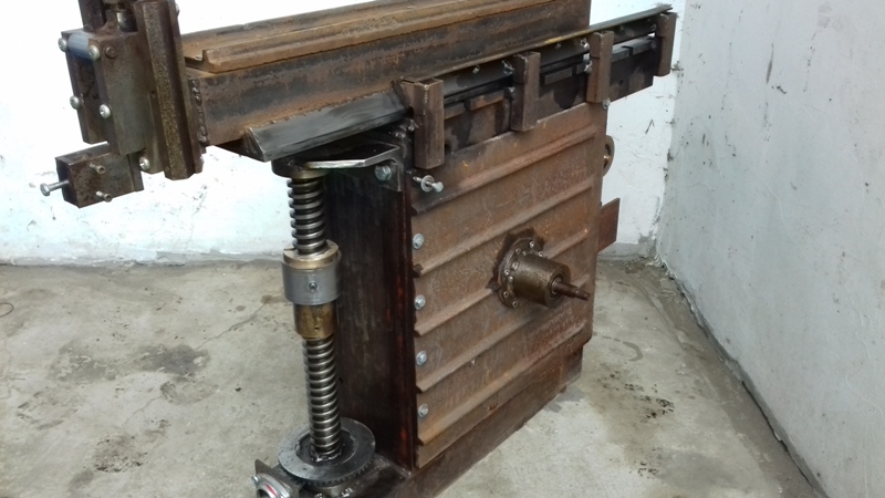
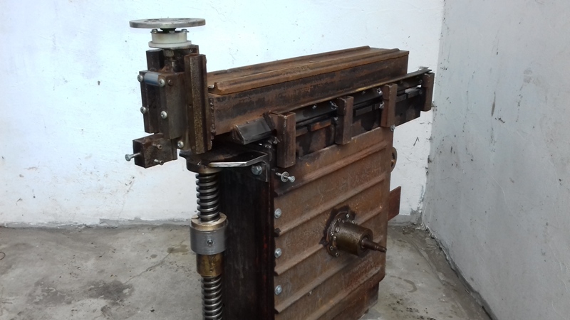
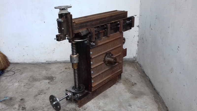
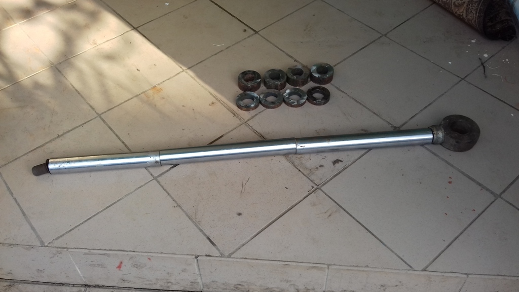
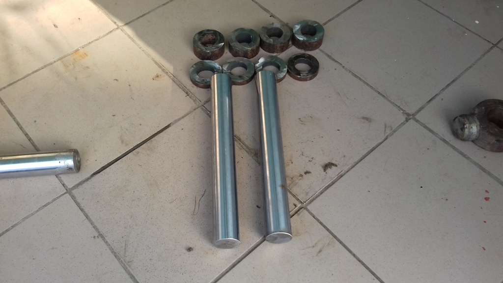
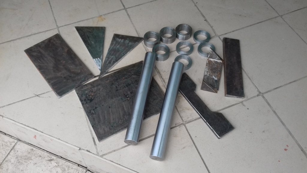
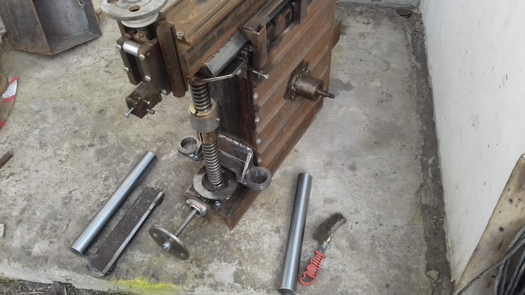
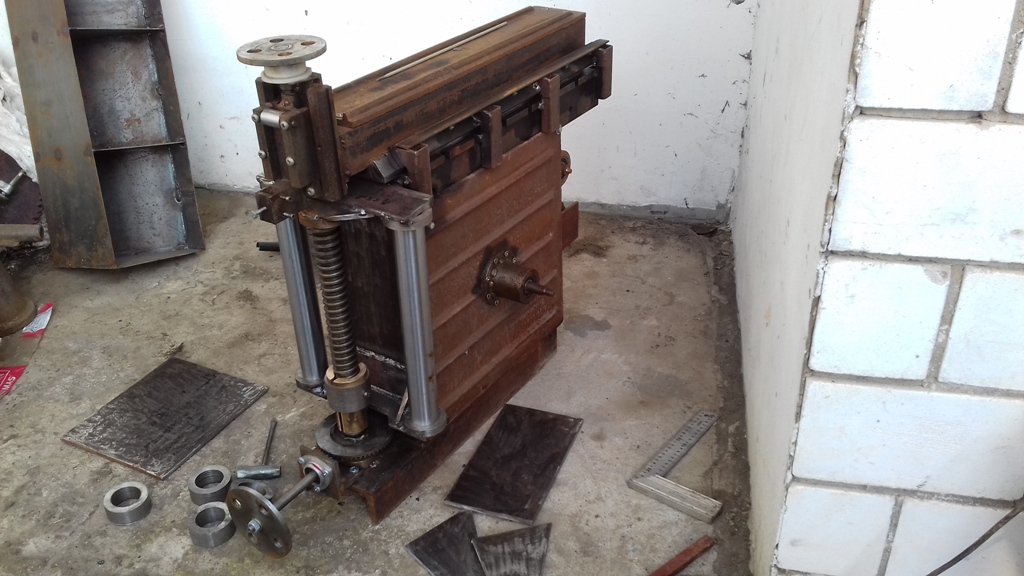
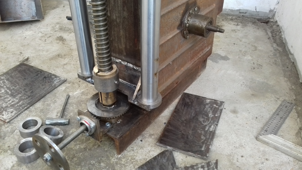
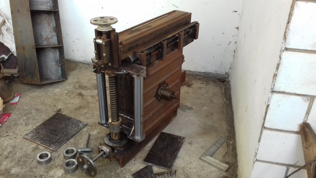
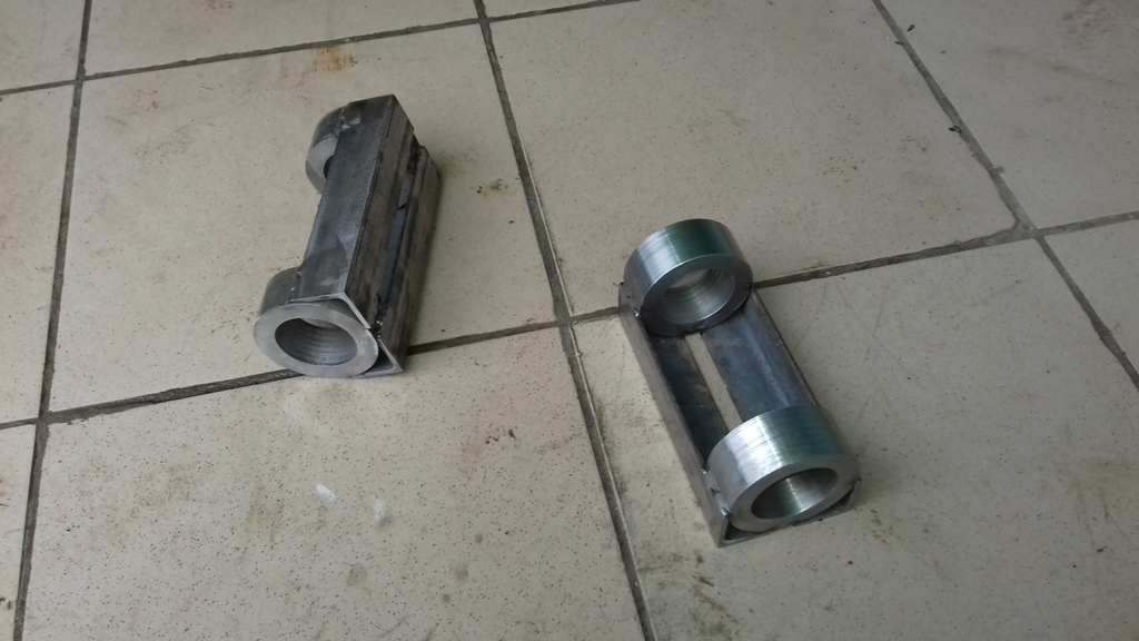
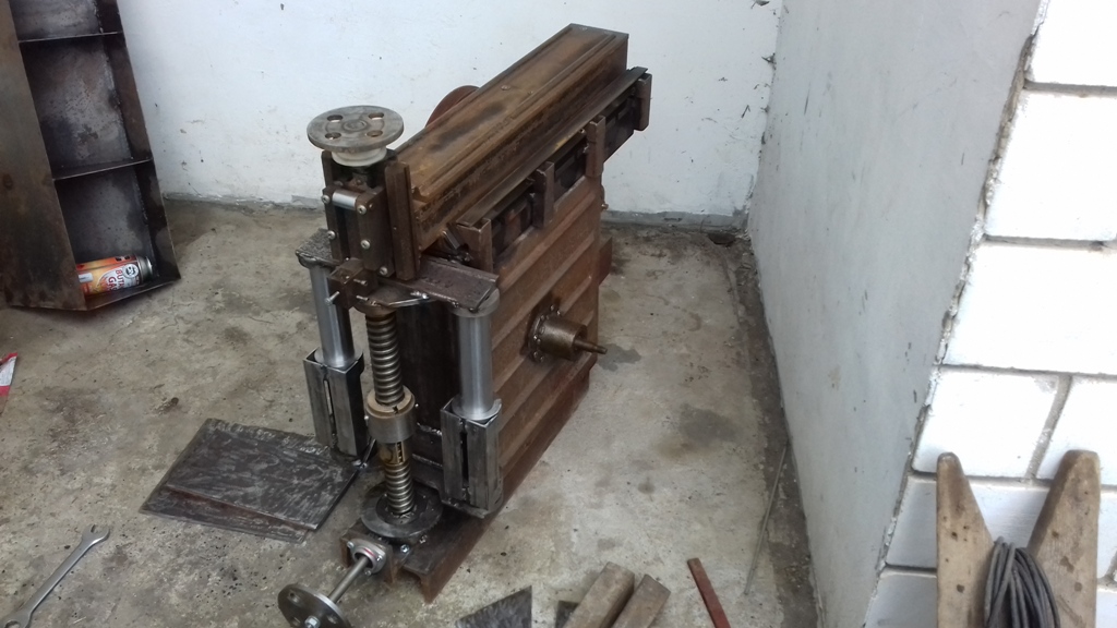
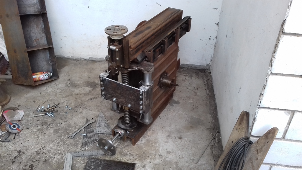
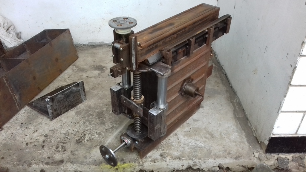
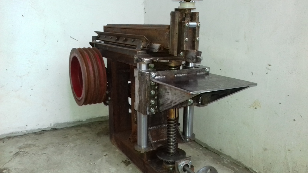
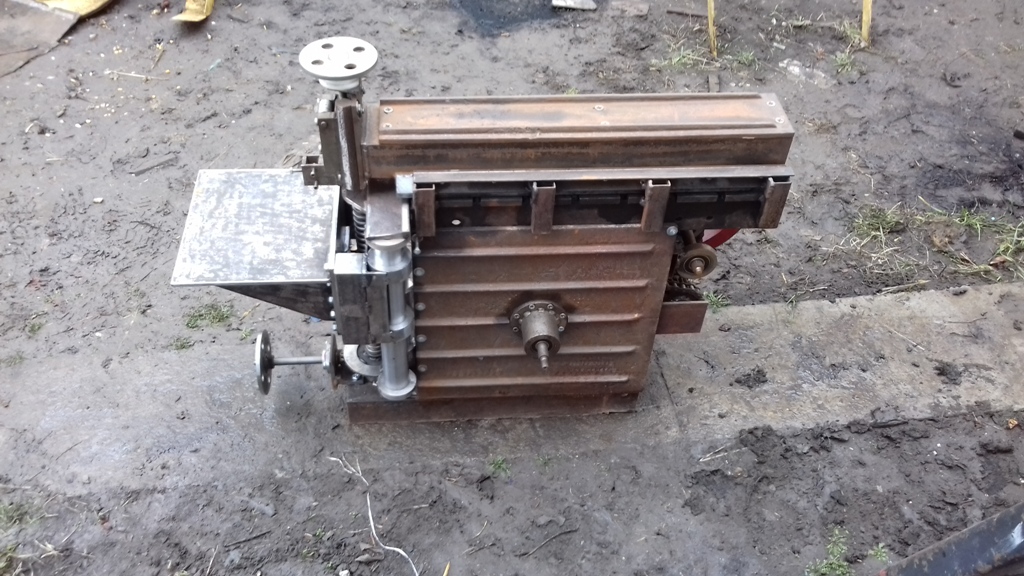
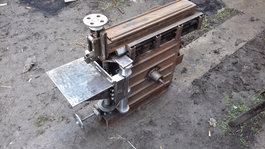
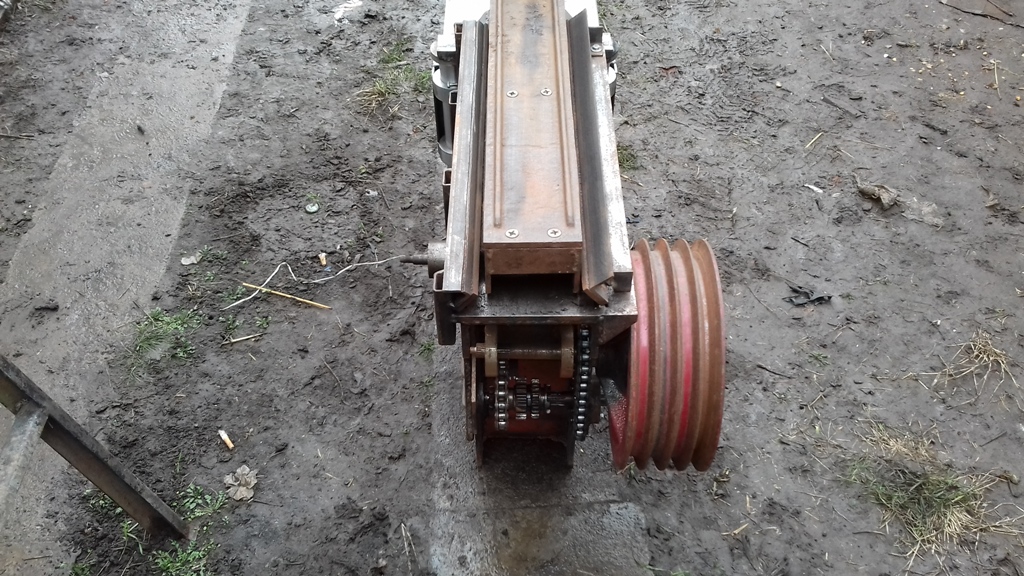
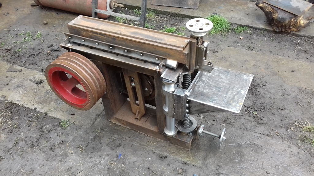
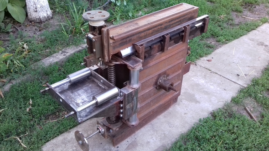
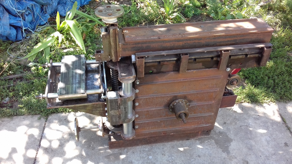
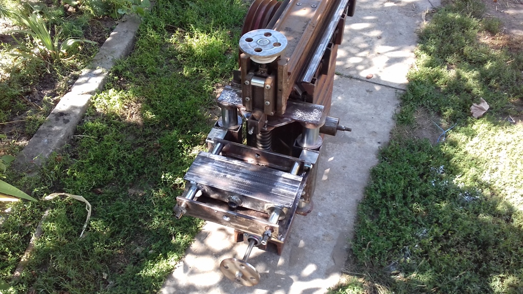
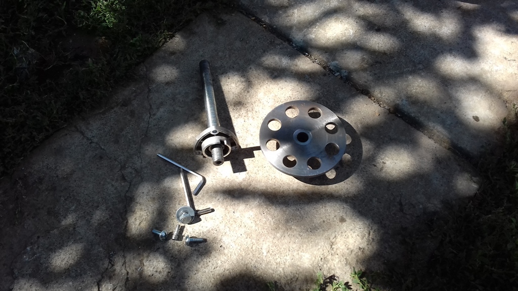
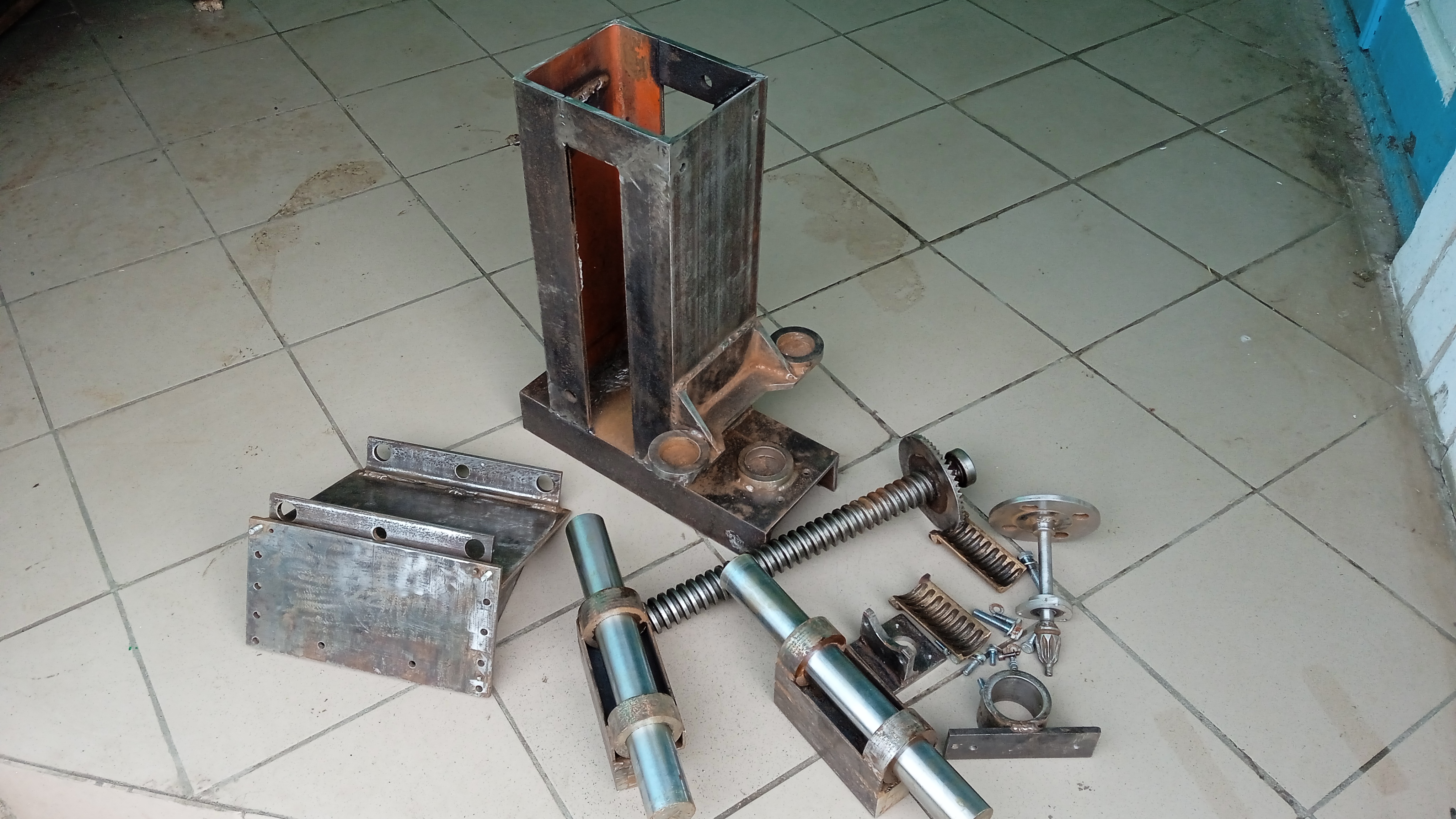
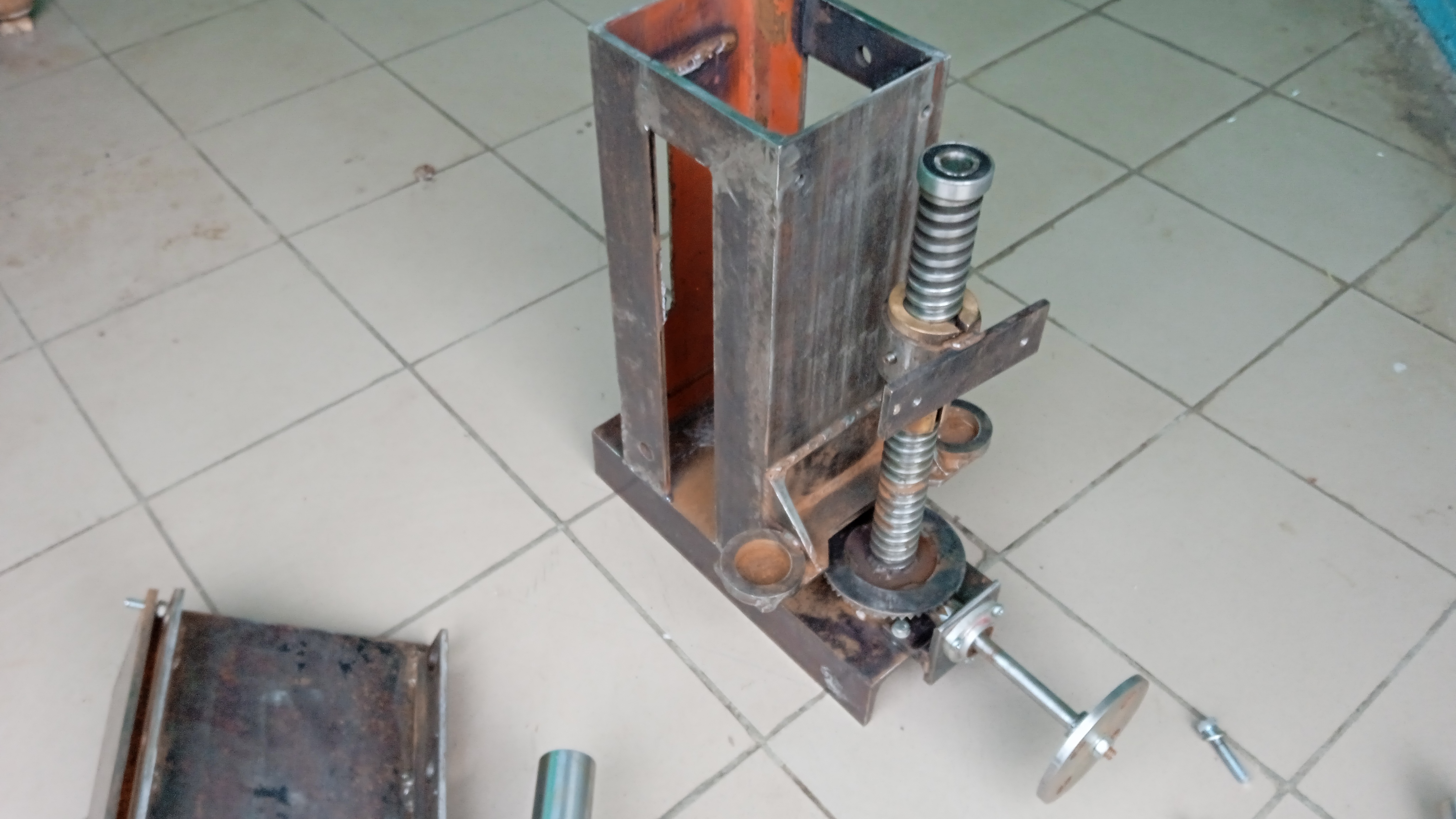
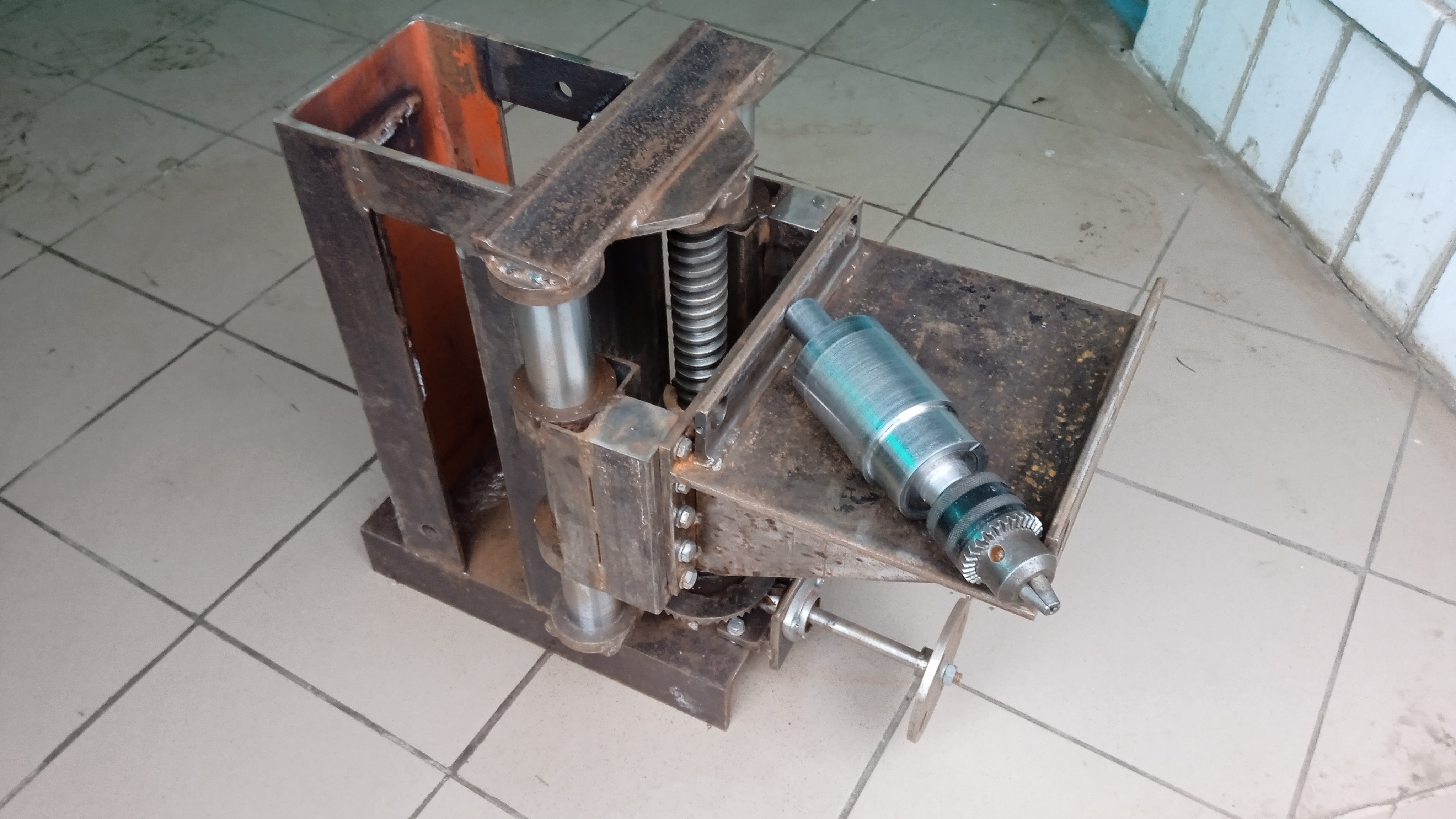
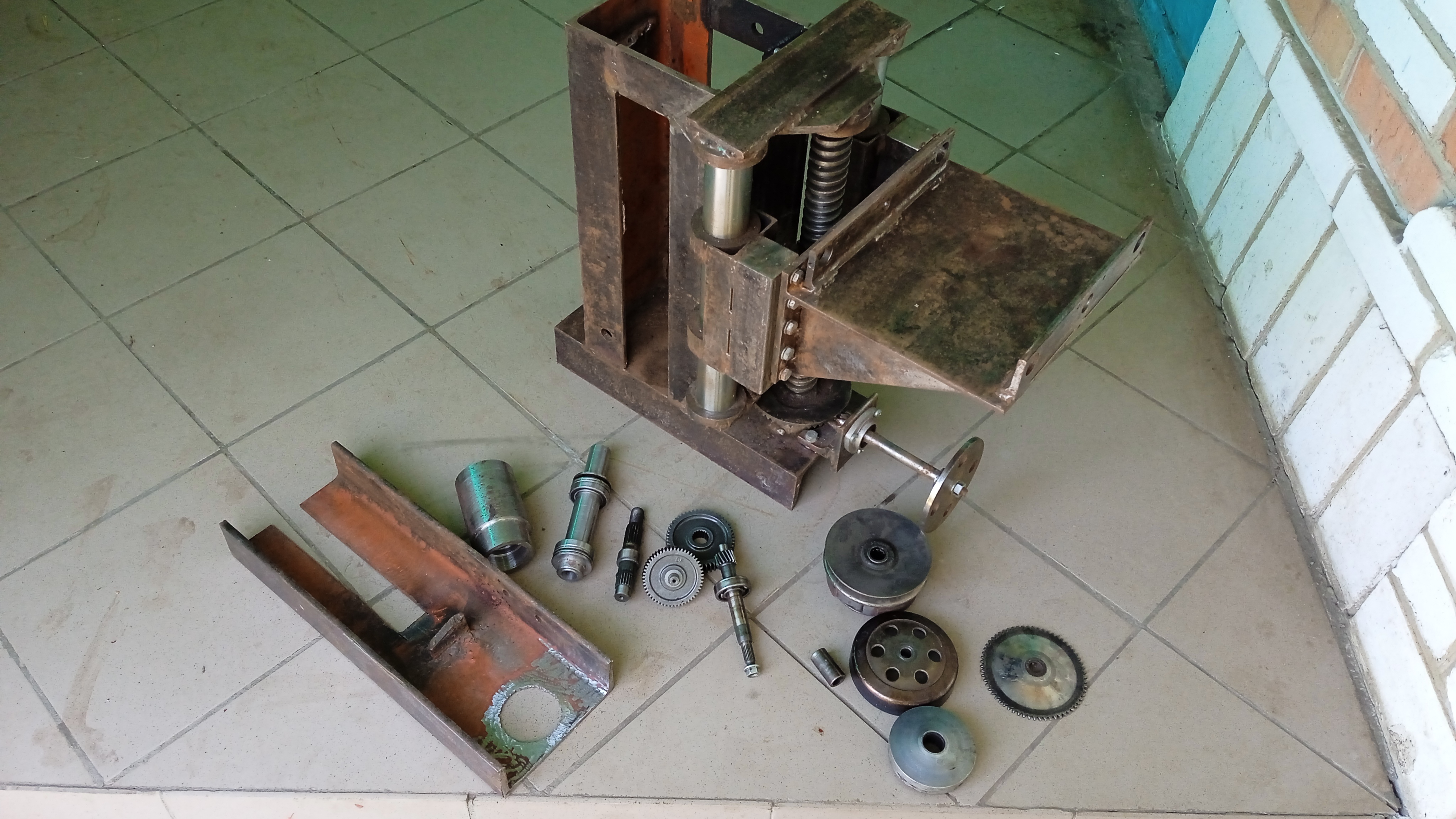
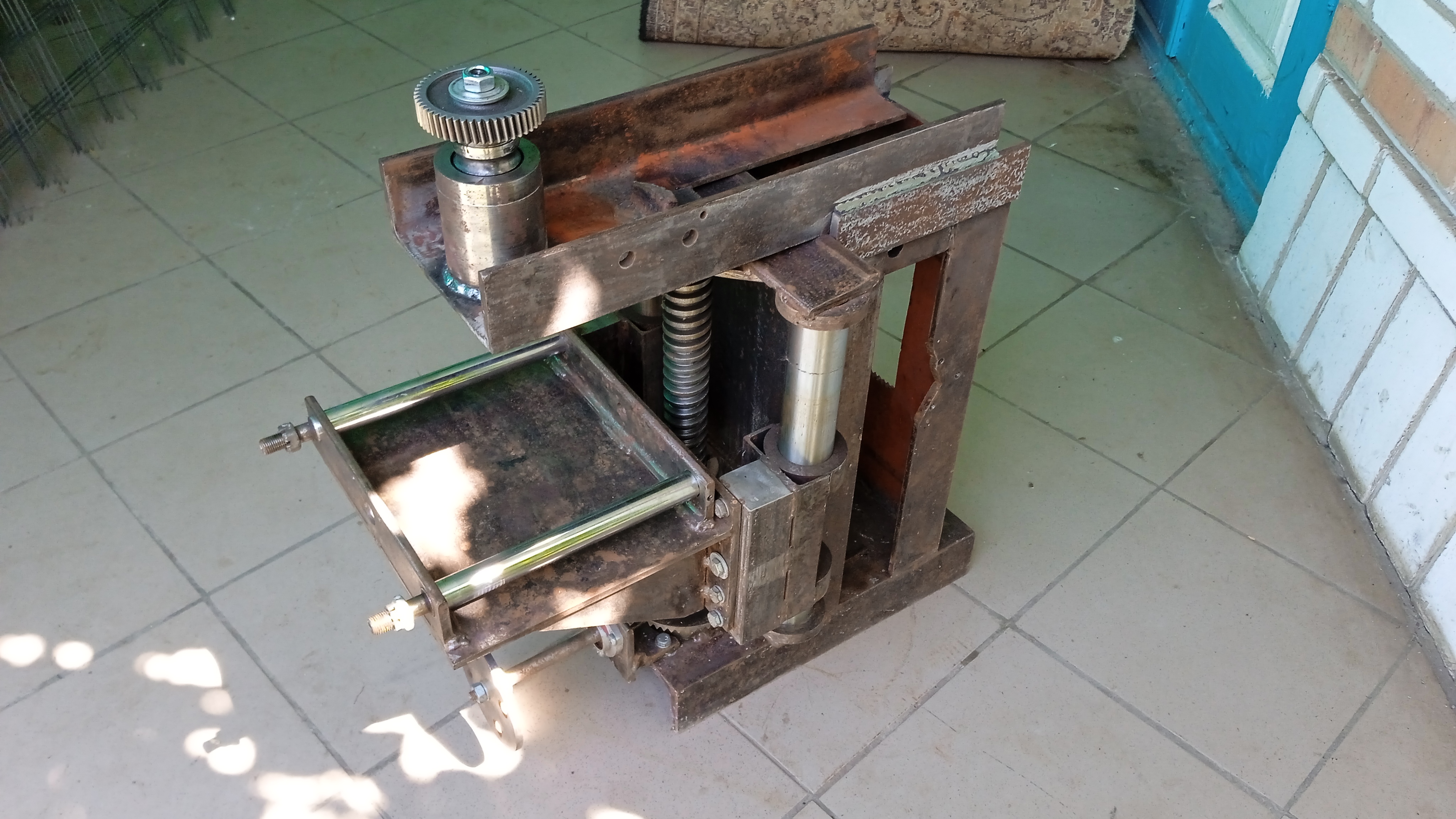
The bed of the metal shaper. To save kinetic energy, a large heavy flywheel is needed. In the photo, a screw 40mm in diameter and a flywheel weighing 15kg. The Metal shaper must be strong and massive .
Attachment 30455 Attachment 30456 Attachment 30457 Attachment 30458 Attachment 30459 Attachment 30460 Attachment 30461 Attachment 30462 Attachment 30463
I've studied your build quite a bit (nice work BTW) and an aspect that isn't clear to me is how the yoke attaches to the ram at the top and compensates for the changing distance between the lower pivot point and the ram's attachment point, i.e. (the distance at yoke vertical from the lower pivot to the ram attachment is shorter than that same distance when the ram is at either end of its travel). Is there a floating link (like in the Gingery shaper) that attaches the yoke to the ram and changes to compensate for the changing distance or is some other method used?
I understand if there's a language barrier to a reply but Google Translate might be of some help.
Very nicely documented with excellent videos. Thank you.
Awesome build. And I have been following your work. Like Crusty's post there are areas of the machine's operation that are a little hard to think through. But I am sure that you have figured this stuff out. This is making me think quite a bit of making my own Shaper.
Who needs a mill when you have a shaper!
AWESOME JOB!
Yes, there a floating link. This mechanism is not yet built, which is why I am not showing it. In the next part, I'll show you everything.Quote:
Originally Posted by Crusty
Something I've been thinking about to deal with that problem is to make the bottom pivot a fixed bearing and the yoke (I call it a yoke for simplicity but I realize it's actually a Whitworth mechanism) extends lower beyond the bearing and it rides against the bearing so that the additional length needed can come from the yoke lower end and the yoke top end is fastened to the ram on a pivot.
Think this would work? Is there an advantage to making it like this?
Thanks for any comments on this approach.
One thing to think about when designing or building a metal shaper is how to de-stroke it to limit the amount of travel the cutter head moves. Since shapers are all designed differently this takes some thought. On a bull wheel and trunion link bar type one way is to move the bottom pivot closer or further from the center pivot another is to cam the center pivot so it moves closer or further from the axis of the bull wheel.
There are many other ways as I said.
I once briefly ran a 30 Hp shaper that had a stroke control from less than an inch all the way to 24 inches the link bars bull wheel and controlling linkages inside were as complicated as a watchmakers pride
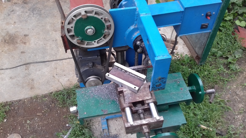
Resumption of work on the project
Attachment 32459 Attachment 32460 Attachment 32461 Attachment 32462 Attachment 32463 Attachment 32464 Attachment 32465
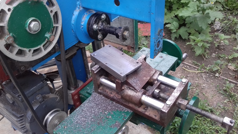
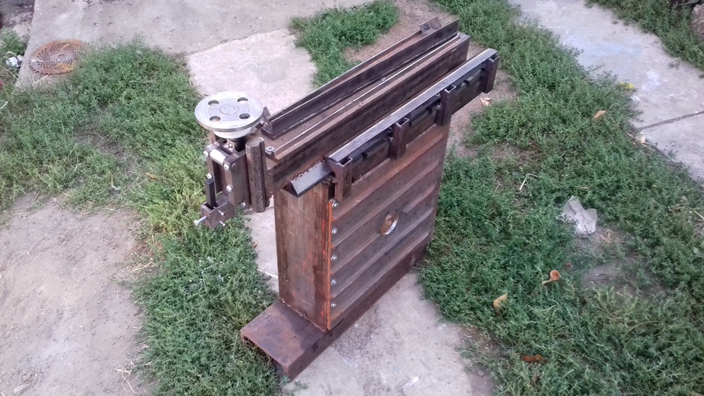
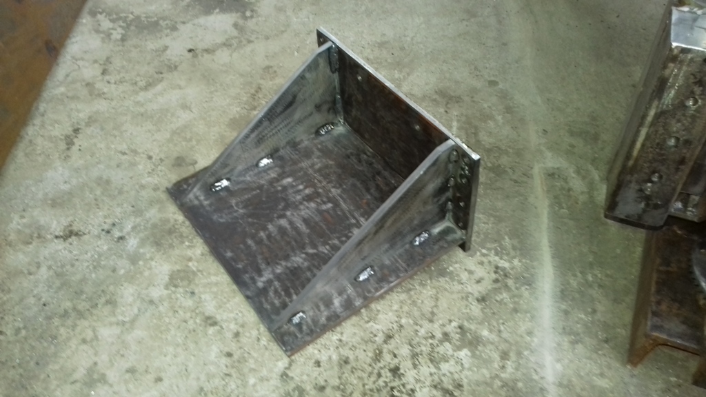
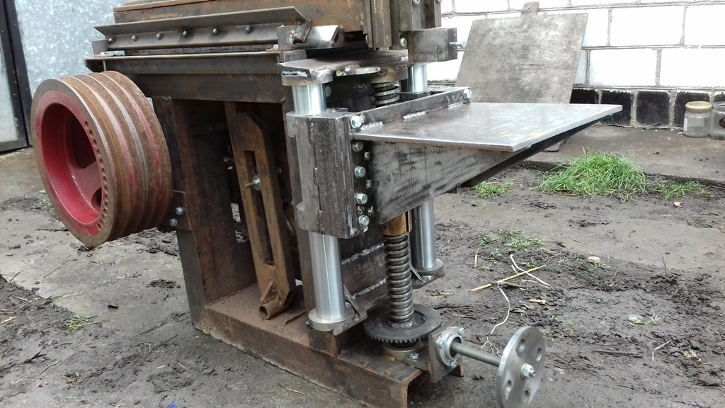
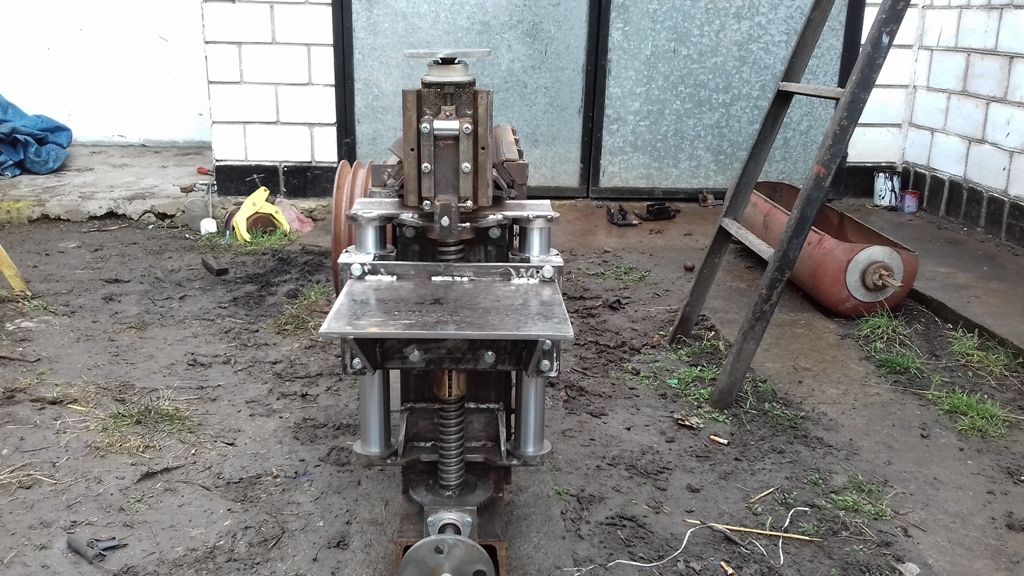
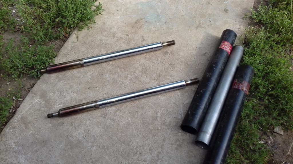
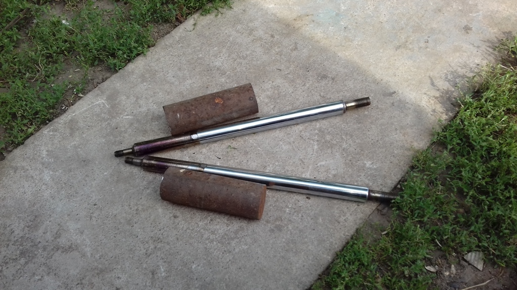
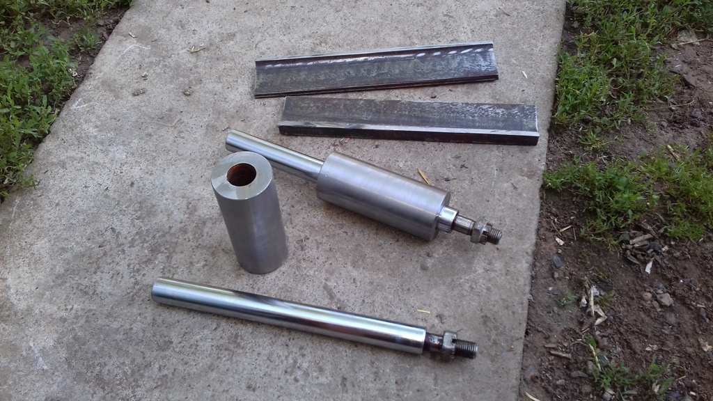
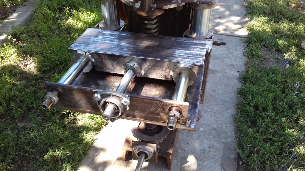
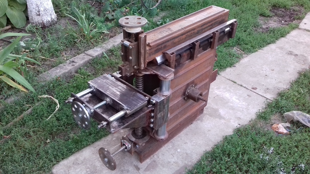
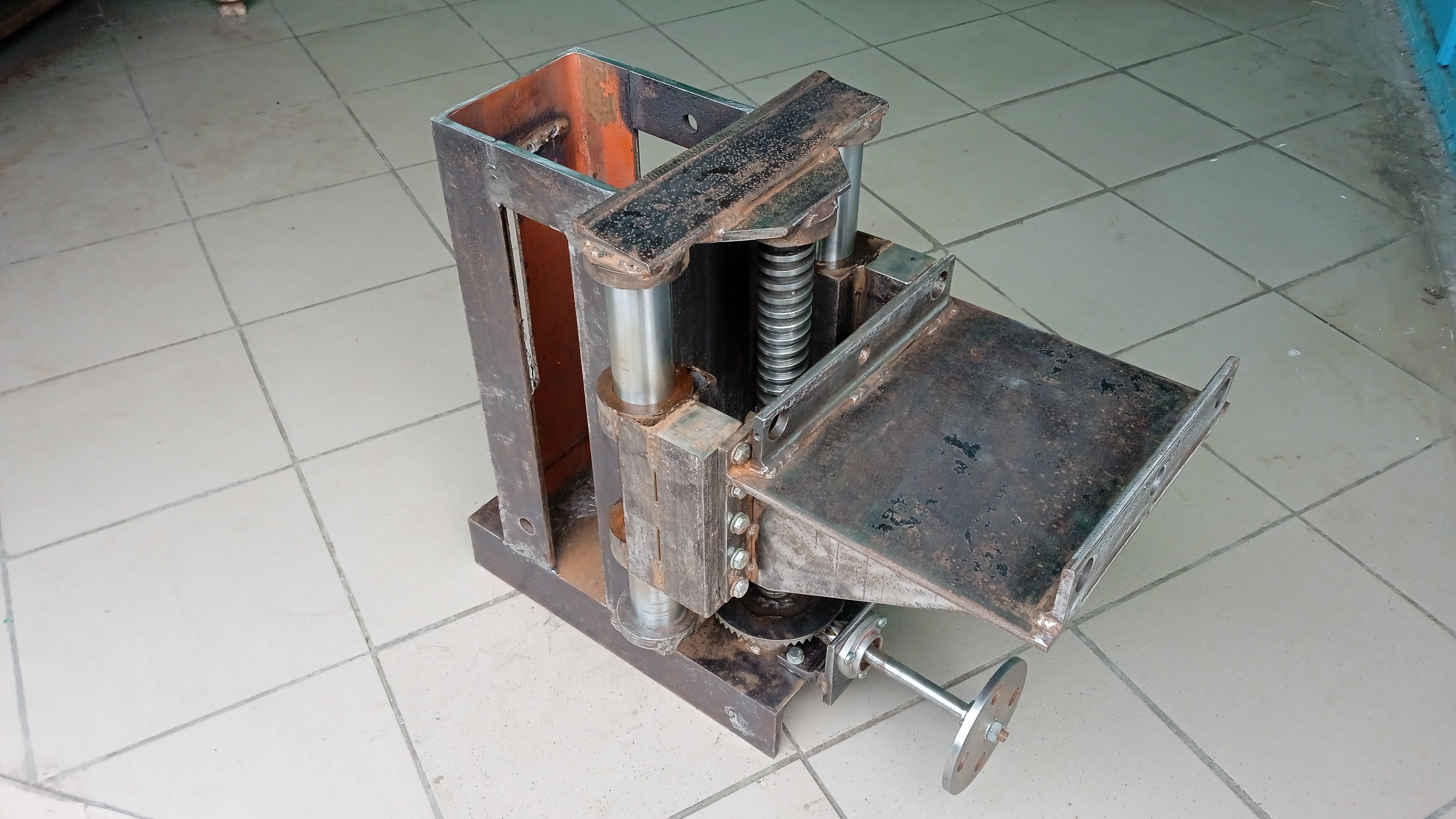
The next stage is the production of the coordinate table.
Z axis is completed. Used a hydraulic rod with a diameter of 45mm excavator hydraulic cylinder, sheet metal 10 mm.Quote:
Originally Posted by Vyacheslav.Nevolya
Hello. After much thought, I decided to finish the metal shaper project. This is a good base for a vertical milling, I need more this machine. A lot has already been changed, expect photos and videos.
https://youtu.be/LLb8DOfCLtY?si=Q8G9PU4I46U8zqEV
https://youtu.be/-r5oek9GVW4?si=7dCoUF-Fp5FXF_gw
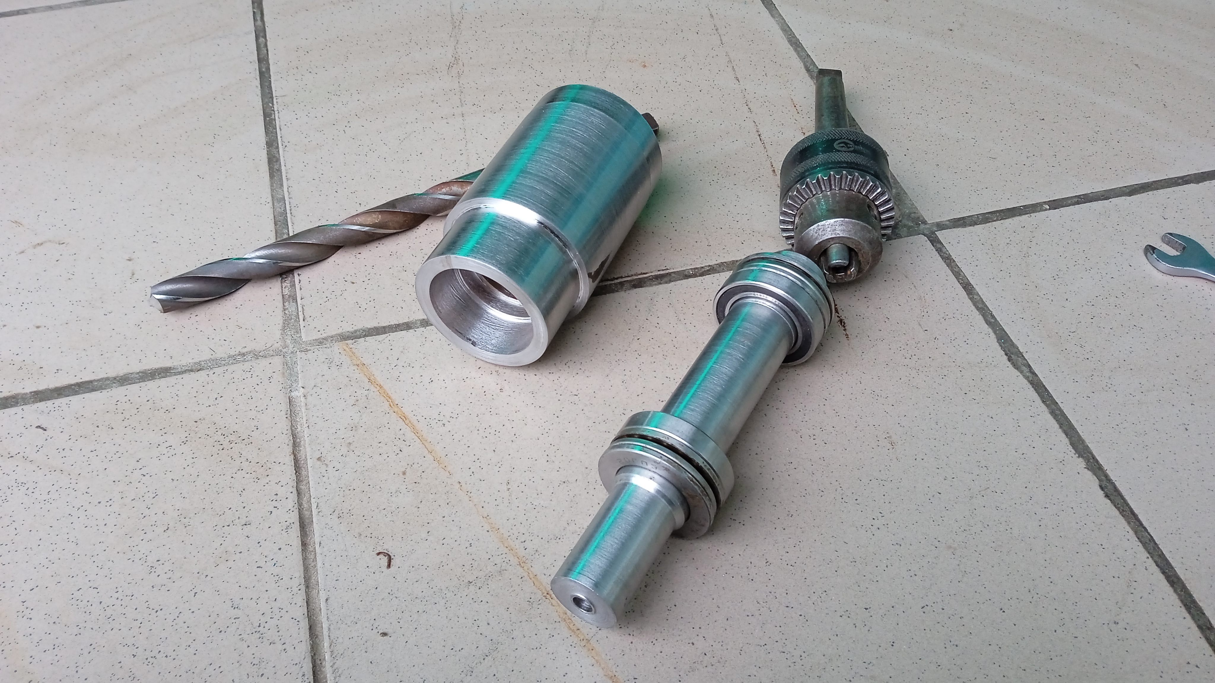
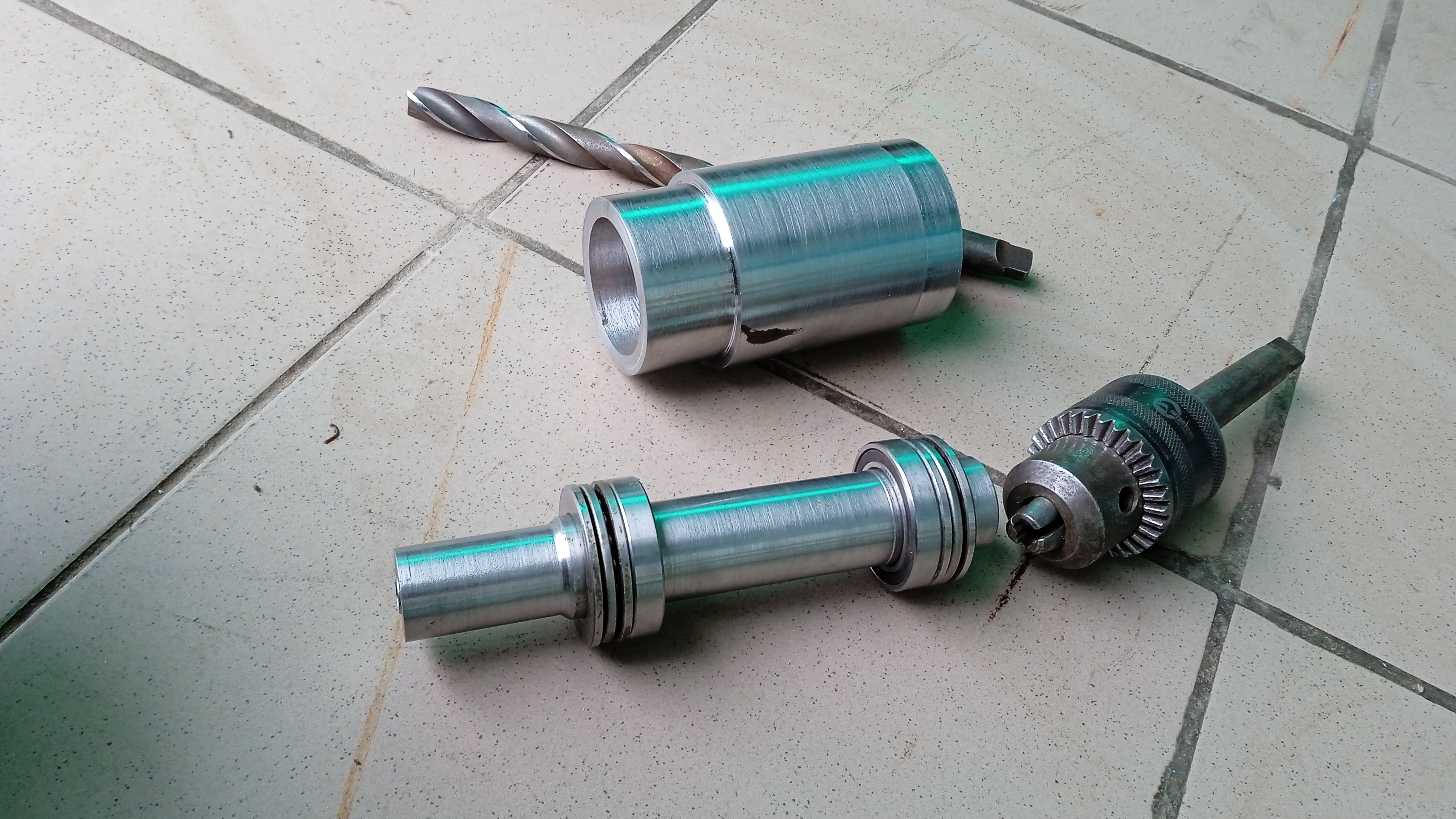
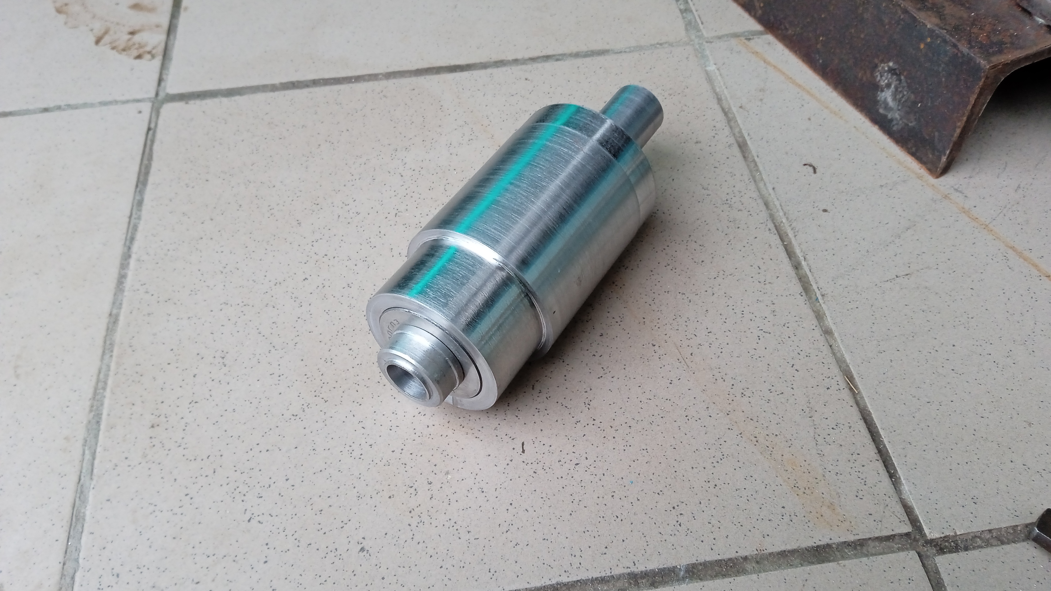
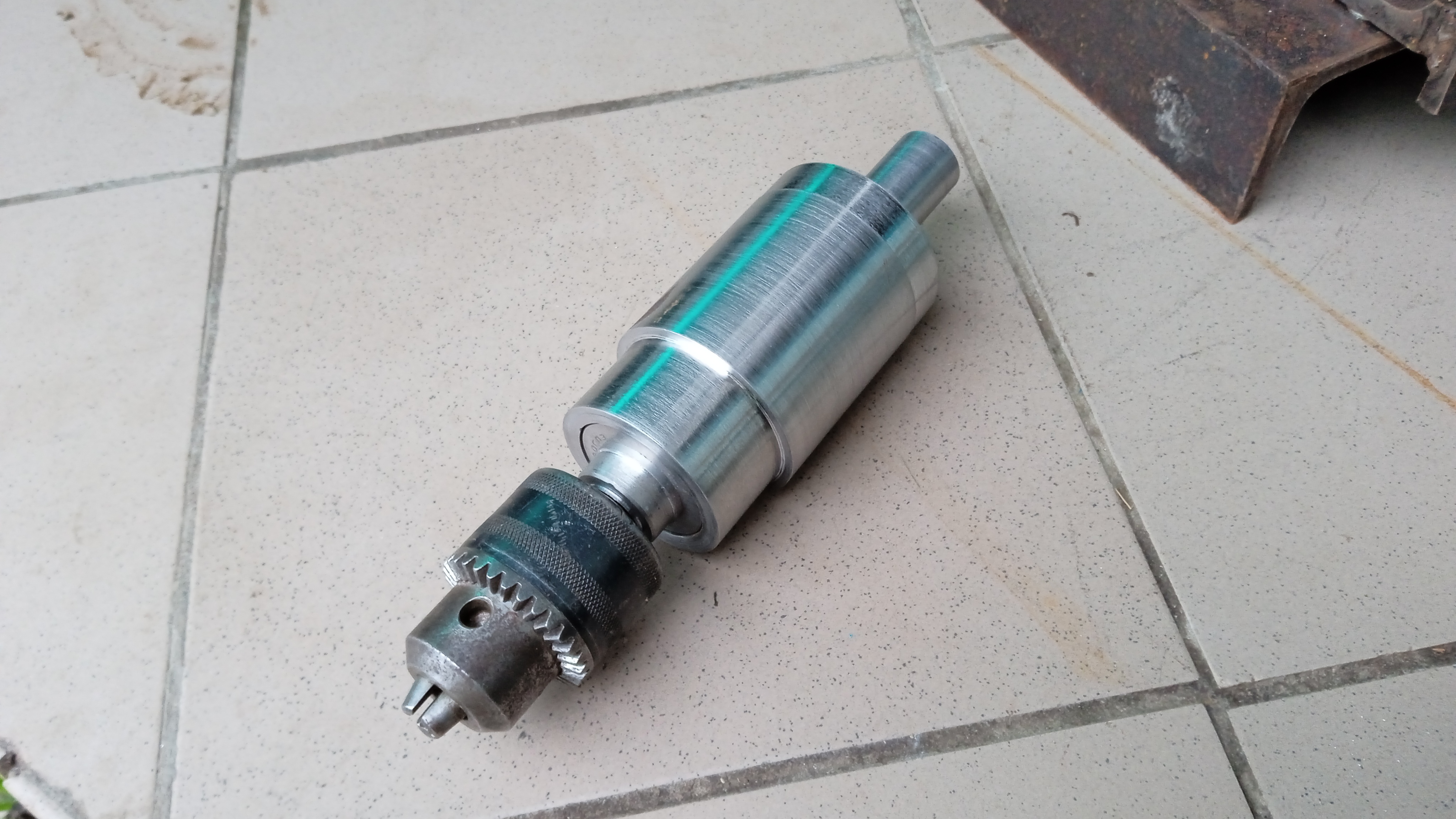
A variator transmission is will bemade to drive the spindle