
 LinkBack URL
 About LinkBacks


My CJ18A ("Real Bull") 7 x 14" from Amadeal in 2017 was delivered with the wrong "Horsepower Resistor", i.e. the current sensing/ limiting resistor -
so the (then freshly marketed as upgraded) 550W or 3/4 hp motor couldn't deliver the torque it should -
as their control board for some unknown reason wasn't accordingly upgraded.
Sharing this might be useful for CJ18A owners out there, who feel that their lathes are lacking grunt, or:
Having an urge to equip their lathe with a load-reading meter, as REAL lathes did back in the days...
Holding no grudge against the supplier who responded promptly - I went for a DIY version (as usual) instead.
At the same time I had some luck in finding two of these in the electronics recycling dumpster at work:
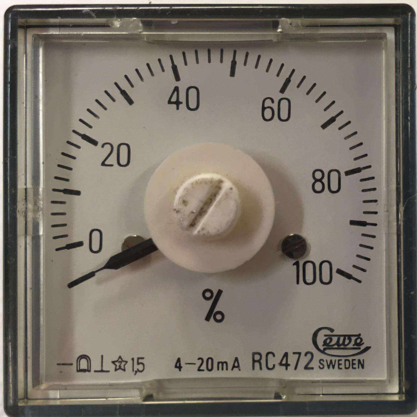
As you see: a 1,5% 4-20 mA industry standard panel ammeter from the seventies with a 49 x 49 mm front.
Great brand, still around and used in power plants over here and a 5% one could even be had today for some 125 bucks.
Sheer luck got me two for free, with better tolerances than store-bought ones.
Thinking it would be great to also be able to have a "quick visual" (apart from just hearing) of the motor's loading when turning.
A few of my smart-a$$ed hi-tech IT colleagues yakked about it being "old-school analogue", which for me is absolutely crucial:
When hogging in, I want a fast and direct, instinctive feel of a scale pointer reading -
NOT having to read some number AND do some math in my head BEFORE EVENTUALLY deciding to ease off or shut down. Enuff ranting.
Here follows a clip from the mail conversation with Amadeal (* refers to KBIC SCR Controller manual):
"Ammeter update (FWIW):
KBIC board supplied with the wrong Horsepower resistor as per the manufacturers instructions:*
Whats mounted is a 0.1 ohm 10 % power resistor (* applicable for 1/3 hp motors) and then
the Current Limit trim pot was instead cranked up to 220% (*rather than to its nominal setting: 150%).
Measuring voltage drop over the HP resistor and motor current with 2 DMMs simultaneously gives the following
(when braking the spindle until the current limiting kicks in):
Hp resistor voltage 0.211 mV @ 2.20 Amps motor current.
So this resistor setup and current trim safely reduces the advertised upgraded 550W motor to a safe 400 W max output
-Not good enough, for yours truly
Board manual* instead states (for a ¾ hp/ 550W motor) a resistor of 0.035 and a 150% CL trimmer level,
where 100% is the nominal 3.3 Amps @ 180 V armature voltage.
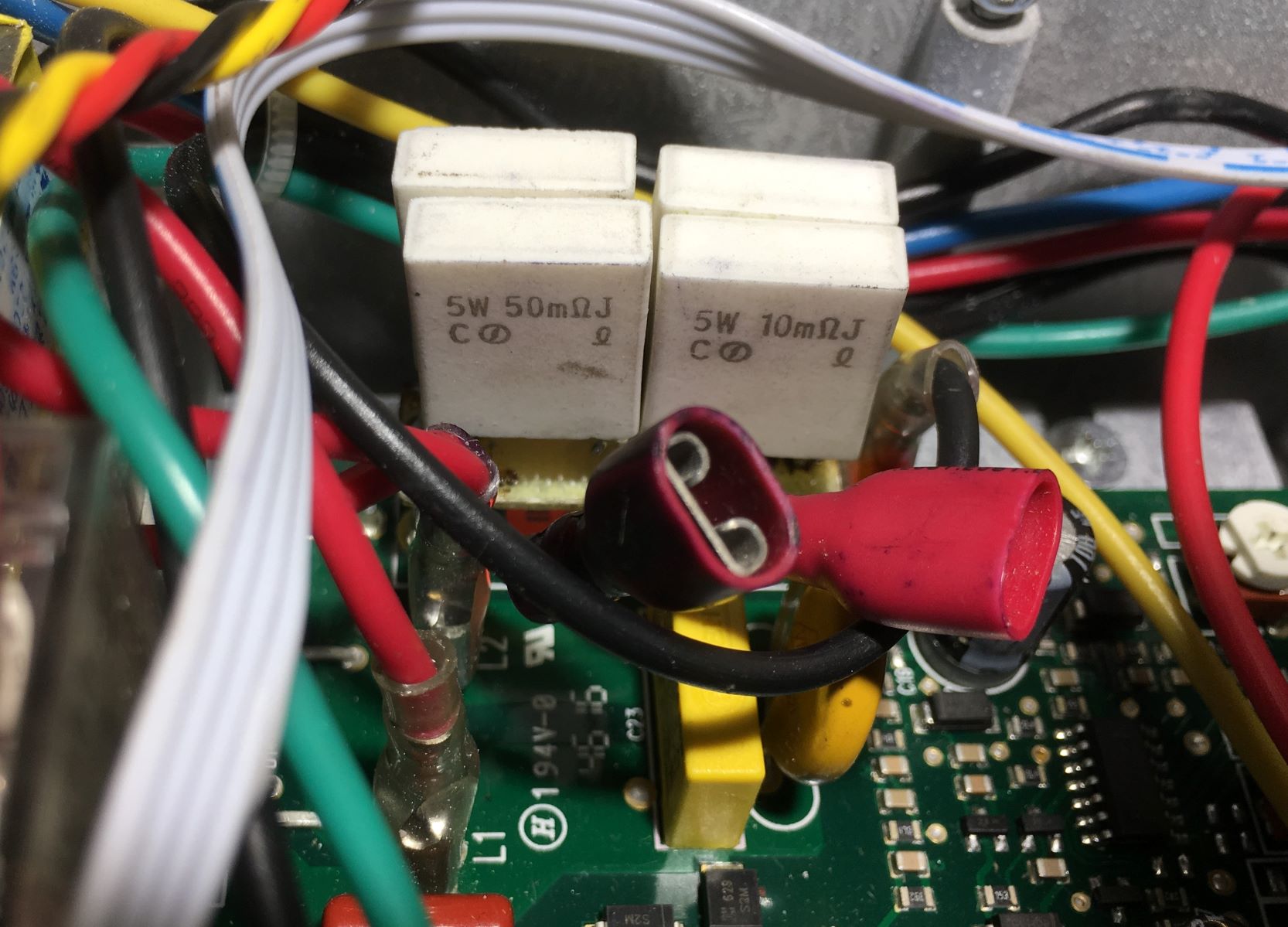
Not having such a resistor I checked my electronics stash and found a coupla used 50 & 10 milli-ohm 5W ones:
When soldered in series-parallel (on the board, instead of the original 0.1 one) they got me the right resistance of 0.030 ohms.
The open connectors will be explained below
Providence then shone its light upon your humble narrator,
so that the voltage drop over this resistor combo was 100 mV @ 3.0 Amps out, but that also reached
the 80% point on my (free) ammeter.
Then: setting the CL trimmer for 120% (instead of the 150 as per instructions) became the FSD point on the meter.
So the ammeter was just be connected in parallel with these two resistors, and itll be up and running!
Simple, cheap (literally!) and fast! "
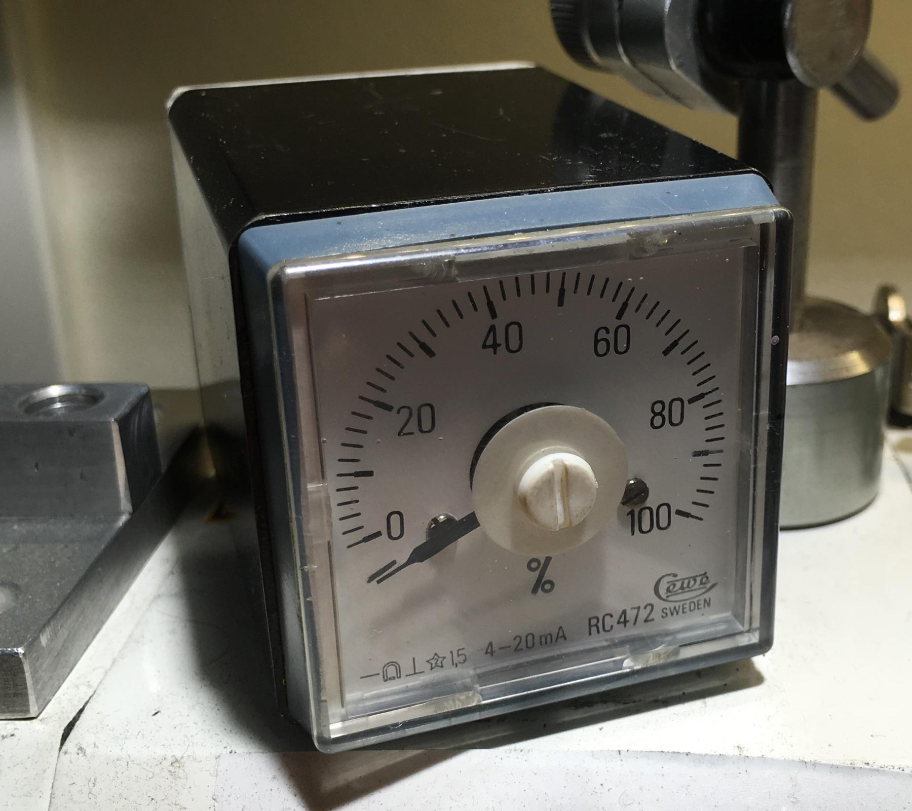
So this is what it looks like today, sitting on top of the headstock:
Meter put in a piece of 50 x 50 mm hot rolled box tubing, sprayed black with two magnets glued at the bottom,
and fitted with a plastic rear end with a cutout for the cable.
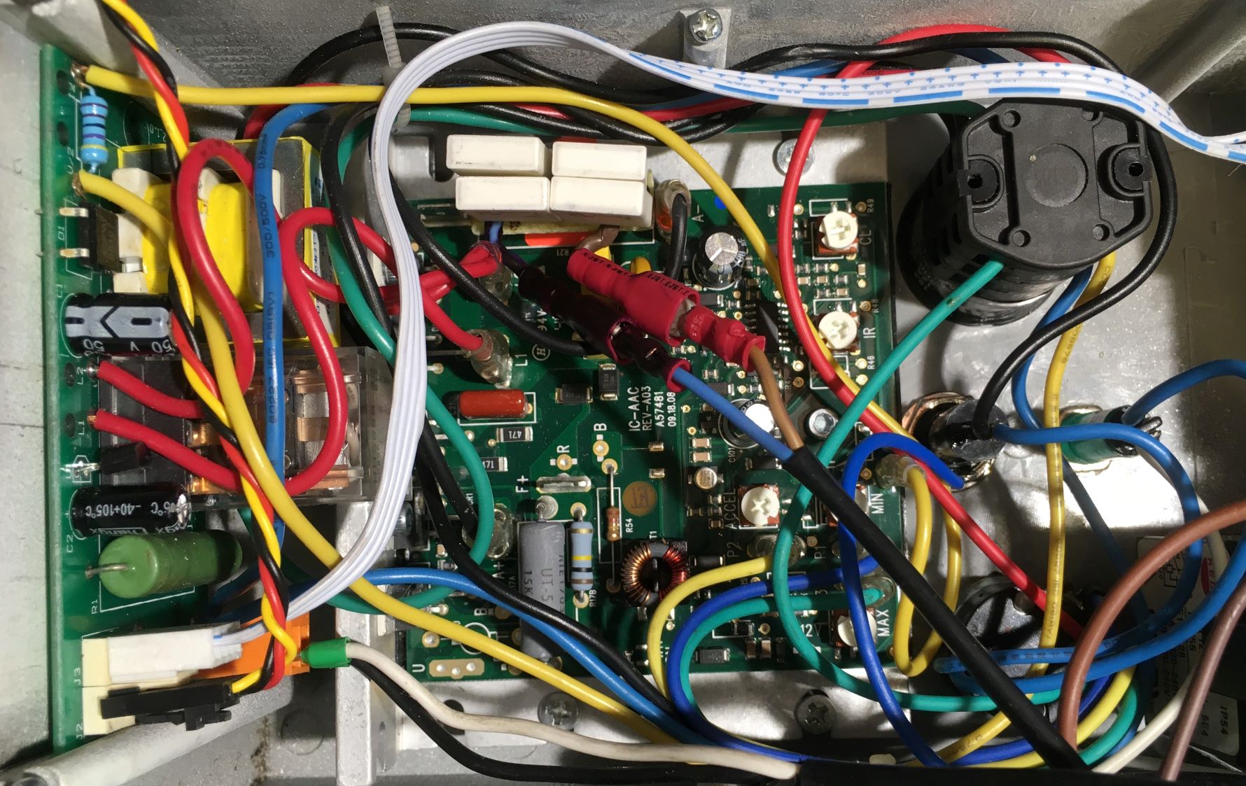
The internals of the control box: HP resistors top centre, then Ammeter cable (max 400VAC) via extra connectors:
Caution: -Though this cable doesn't conduct high current, it is at live voltage, and should thus be properly insulated and installed
(tip: nicely fitted under the cable shield running up to the Chuck guard breaker).
Mission completed: Now the motor can deliver, AND I can instantly see how much it works. All this for free!


 Reply With Quote

Bookmarks