
 LinkBack URL
 About LinkBacks


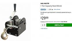
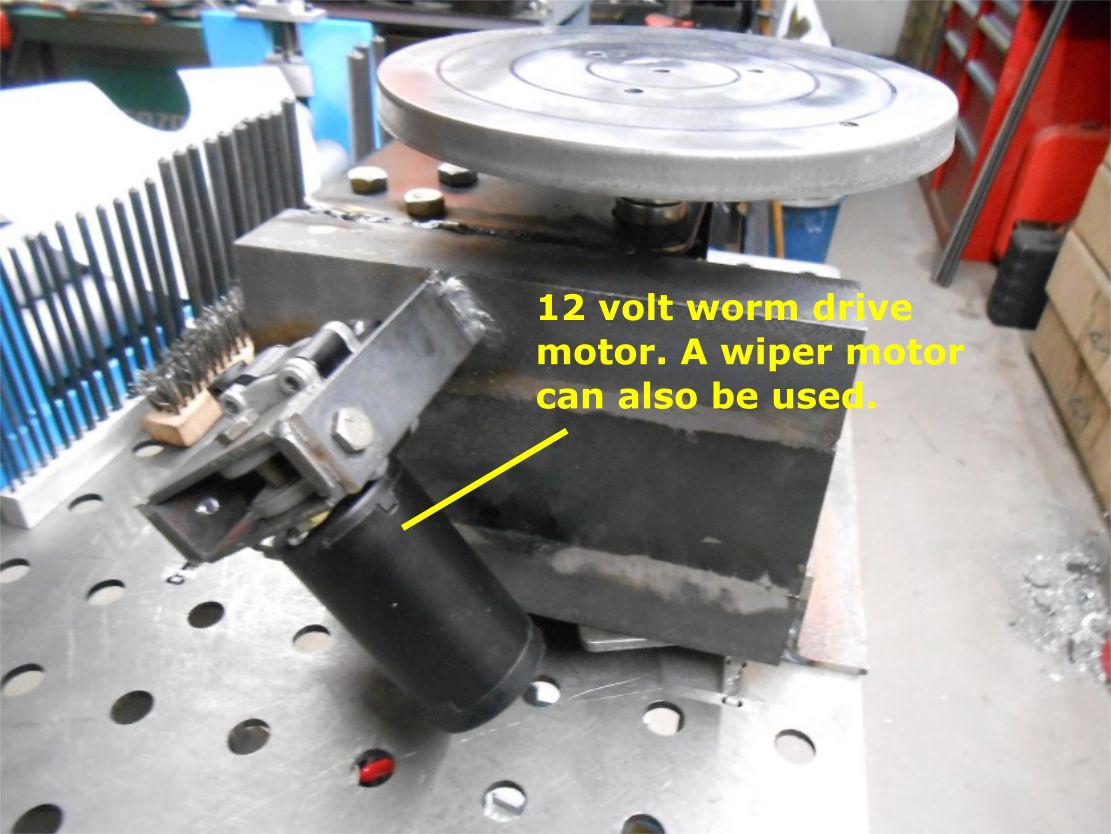
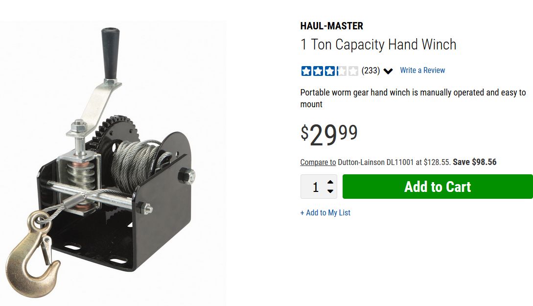
This is my Franken-cobbled motorized weld positioning table! It's made from a Harbor Freight trailer hand winch and 12 volt worm drive motor. (a wiper motor can also be used)
The winch itself is NOT very useful as a winch (lol) as this has about a 40:1 ratio. You would spend most of the afternoon winching your car or boat up using this.Also, both gears are not hardened so using them to pull a heavy load would wear them out quickly! (has terrible reviews)
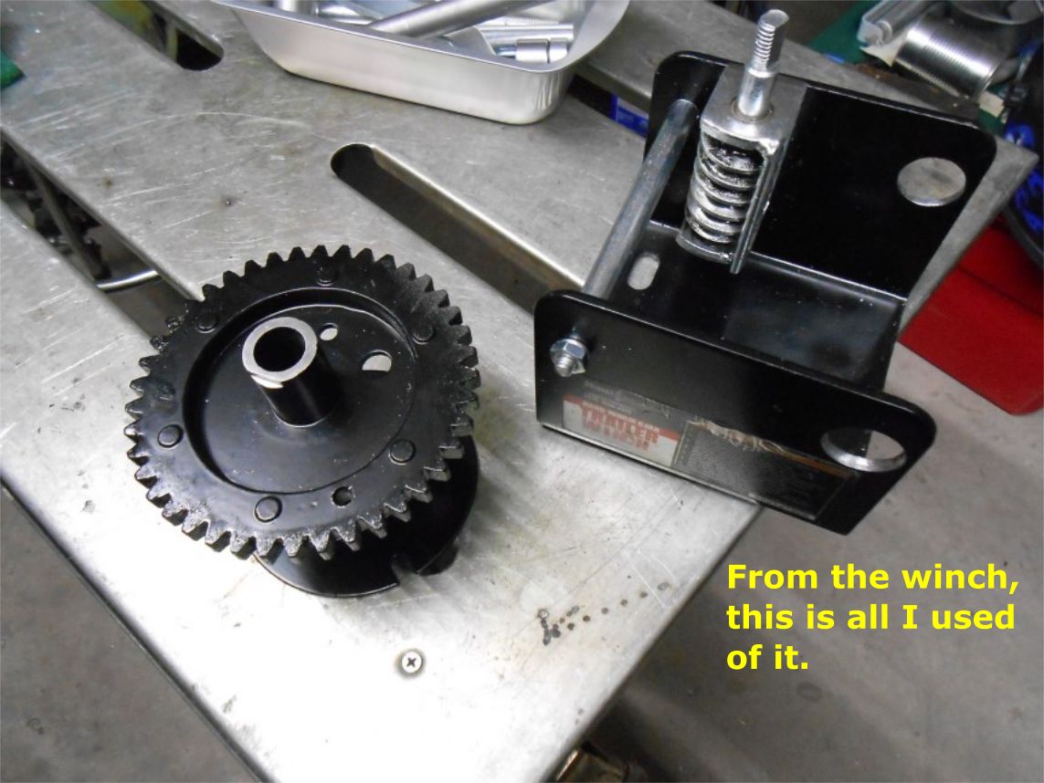
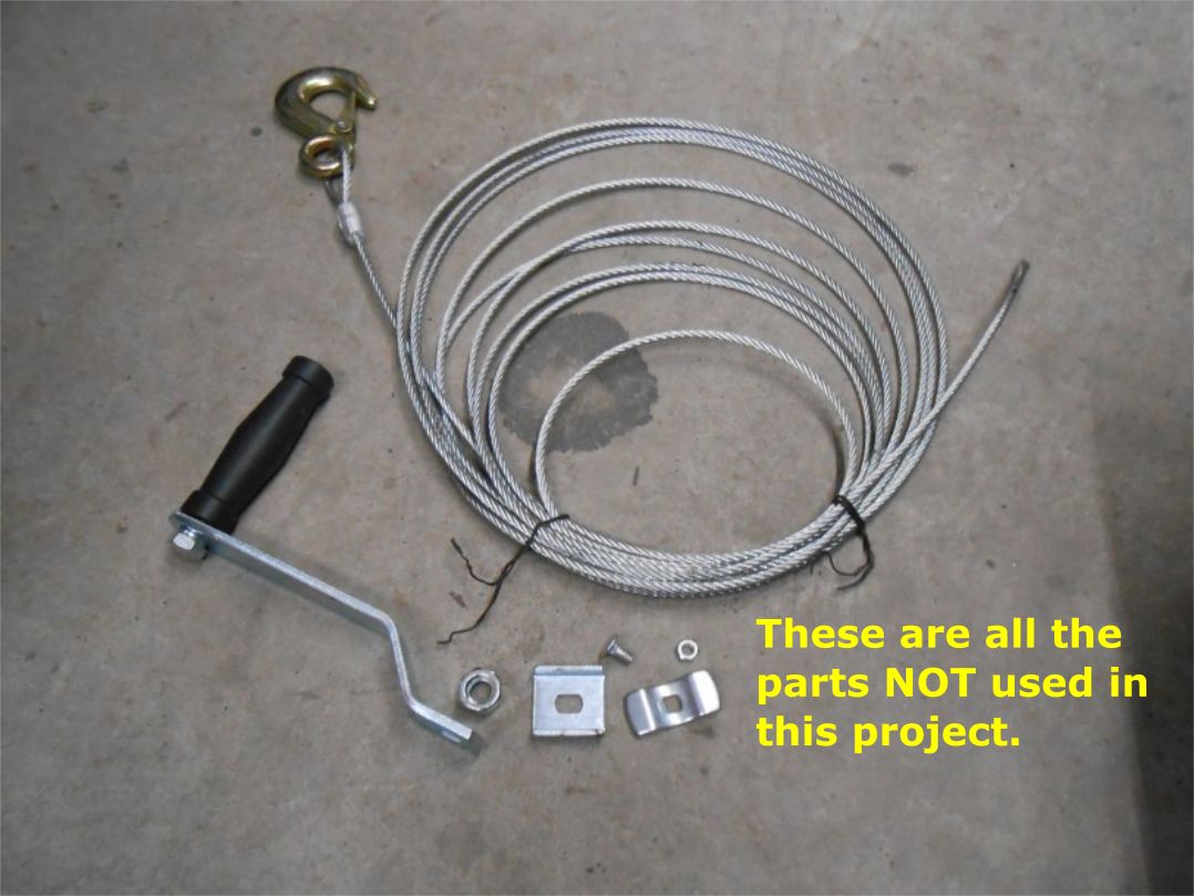
It is however a GREAT starting place to build a rotary weld positioner! Just cannibalize the needed parts; worm drive, drive gear and housing and your well on your way. There are many parts left over (bonus) that can be used for future projects. (see pics)
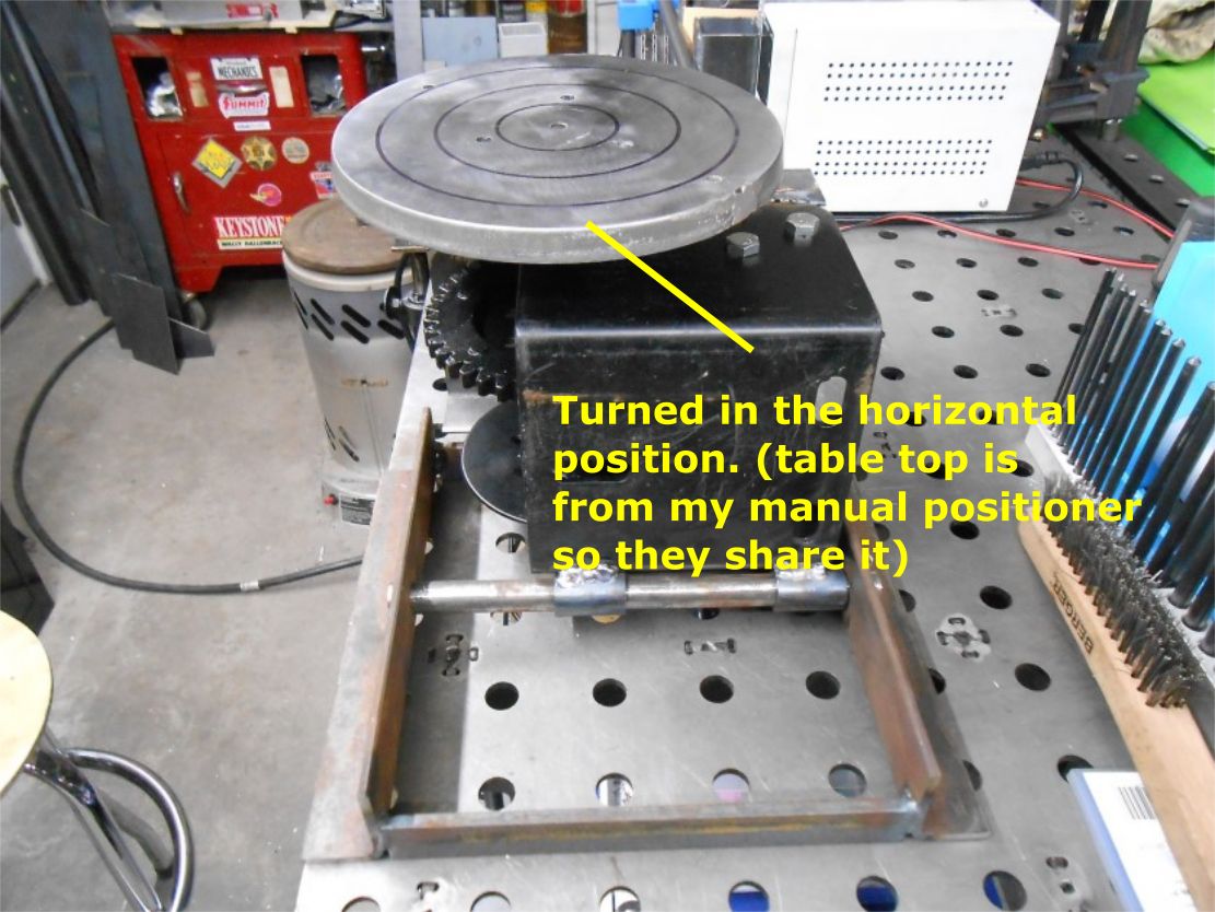
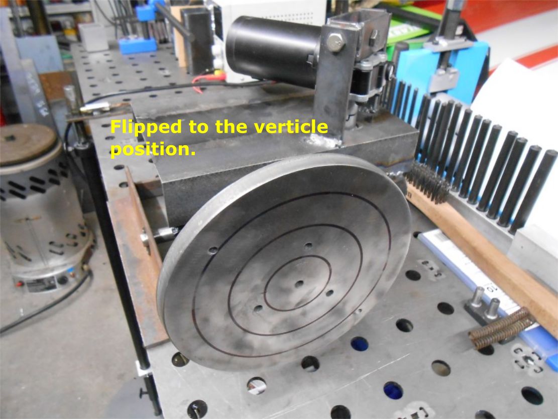
This version features both horizontal and vertical positions. I was not going for beauty but rather function and I think I nailed it! lol Probably won't even paint this, just use it as is. (and make improvements as needed)
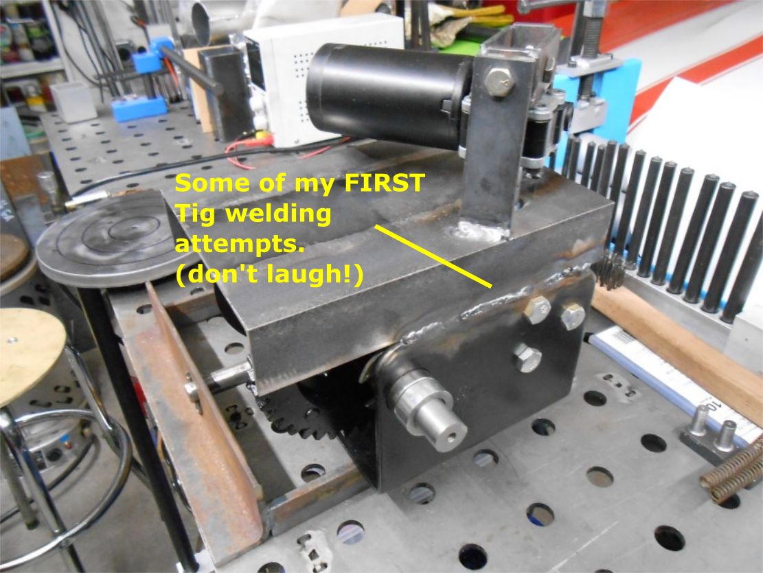
I've run this from an adjustable power supply from 2 volts up to 30! You won't be welding anything at 30 volts but down around 3-3.2 volts looks about right. (have to time it yet, I heard 1/8" per second is about correct for Tig welding)
If you want fancy, this one is not for you but if you want a cheap & functioning positioner, this fits the bill!


 Reply With Quote

Bookmarks