Free 186 More Best Homemade Tools eBook:  
Get 2,000+ tool plans, full site access, and more.

User Tag List

Page 1 of 2 1 2 LastLast
Results 1 to 10 of 11

Thread: Mounting an AXA QCTP on a 9x20 lathe

  1. #1
    Supporting Member Crusty's Avatar
    Join Date
    May 2019
    Location
    Dry Gulch, Tx
    Posts
    749
    Thanks
    220
    Thanked 845 Times in 324 Posts

    Crusty's Tools

    Mounting an AXA QCTP on a 9x20 lathe

    Upgrading my lathe I bought a QCTP (quick change tool post) and it came with a base and mounting stud, however using the base will make your tools locate above center at the lowest position. The factory stud in the top of the compound is way too small and that allows the tool to wiggle under even a moderate cut. I first wanted to use the supplied stud and modify my compound for it but the threads on it were 9/16"x18 (not M15 commonly declared on the interwebs), an uncommon size that I didn't have a tap for.

    Mounting an AXA QCTP on a 9x20 lathe-base-bolt.jpg

    The next larger common size was M16 but it wouldn't fit through the center of the tool post, but I bought some M16x100mm bolts any way and threaded the compound for that size since I already had a tap for that thread.

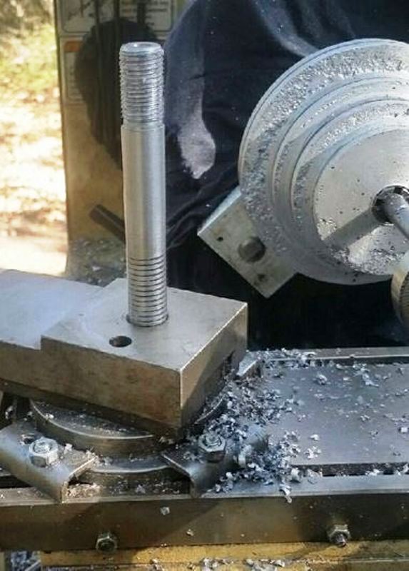
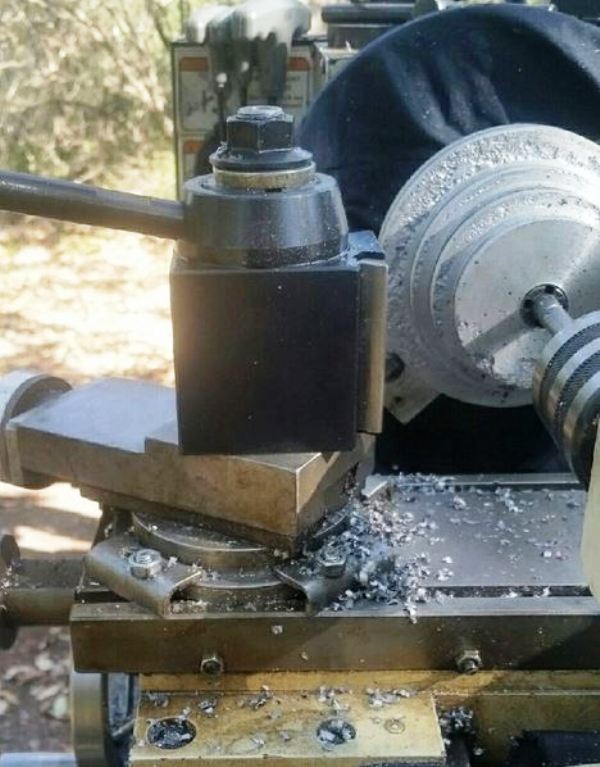
    Then I mounted the bolt between the chuck and the live center and turned all but the bottom threads down to 9/16" and single point threaded the other end to fit the supplied flange nut. Since a 100mm length would be tight with the SAE thick washer I intended to use under the flange nut I trimmed off the corners of the hex head so that when I turned the shank down I got an additional 8-10mm of stud length.

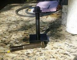
    Here's the new stud mounted into the compound using 262 Loctite (red).

    Mounting an AXA QCTP on a 9x20 lathe-stud.jpg

    Tada! Bob's your uncle and it's much more rigid cutting now.


    Mounting an AXA QCTP on a 9x20 lathe-qctp-mounted.jpg

    186 More Best Homemade Tools eBook
    Last edited by Crusty; Dec 2, 2020 at 01:30 PM.
    If you can't make it precise make it adjustable.

  2. The Following User Says Thank You to Crusty For This Useful Post:

    olderdan (Dec 3, 2020)

  3. #2
    Supporting Member metric_taper's Avatar
    Join Date
    Mar 2017
    Location
    Marion, Iowa
    Posts
    585
    Thanks
    227
    Thanked 256 Times in 153 Posts

    metric_taper's Tools
    Looks like you have those infamous step pulleys. I can't tell what kind of expanding mandrel you have there. I've seen the type that has a tapered axle with centers on each end, and then a sleeve that has the inverse of that taper that was cut into sections that lets it expand on the mandrel.
    I have used that on my lathe the issue I ran into is I could not drive enough torque into the work. And if I recall it's hardened steel, the drive dog set screw could not bite in, as it was slipping also.

    2000 Tool Plans

  4. The Following User Says Thank You to metric_taper For This Useful Post:

    olderdan (Dec 3, 2020)

  5. #3
    Supporting Member metric_taper's Avatar
    Join Date
    Mar 2017
    Location
    Marion, Iowa
    Posts
    585
    Thanks
    227
    Thanked 256 Times in 153 Posts

    metric_taper's Tools
    I'm thinking this is the type you have:

  6. #4
    Supporting Member olderdan's Avatar
    Join Date
    Jun 2016
    Posts
    781
    Thanks
    1,456
    Thanked 1,531 Times in 463 Posts

    olderdan's Tools
    I was given two of these between centres expanding mandrels, they are mostly used for finish grinding opps. Trouble is the more they expand the more the sleeve goes hollow in the centre so they will only grip on the outer edges of a bore,I dont use them much on the lathe.

  7. #5
    Supporting Member Crusty's Avatar
    Join Date
    May 2019
    Location
    Dry Gulch, Tx
    Posts
    749
    Thanks
    220
    Thanked 845 Times in 324 Posts

    Crusty's Tools
    No, those are the first type. I made a drive dog for driving them using a slot in a face plate. If I remember right I used a 1/4-20 bolt to engage the flat on the mandrels.

    Those expanding collets and tapered mandrels make a significant improvement in my work quality.

    I dunno about the particulars of how they're made but it looks like a straight matching taper inside the collets to me and if the taper angle matches the mandrel taper then the collet outer surface should remain parallel as it expands. I do know that they hold my pulley castings well and when I'm finished my turned pulleys run as true as you could ask for. That one shown in the lathe is actually too small for the pulley bore so I've got a 15 thou brass shim inside the bore and the mandrel is driven to nearly bottomed out, and I seated the mandrel into the collet with a dead blow swing press* so it's tight.

    This thread's focus however is on a new stud for mounting my QCTP.

    Thinking about it some more I wonder if the hole quality might be the root cause of the issue that you have with those mandrels and collets. All my bores are first rough drilled and then finish reamed to a straight, precise bore and the collets appear to me to seat properly in them. When I turn that pulley around for counter boring the bottom I'll inspect the shim that I have in there and I may be able to tell if I was only gripping the pulley at the ends or not.

    *swing press = hammer☺
    Last edited by Crusty; Dec 3, 2020 at 08:55 AM.
    If you can't make it precise make it adjustable.

  8. #6
    Supporting Member metric_taper's Avatar
    Join Date
    Mar 2017
    Location
    Marion, Iowa
    Posts
    585
    Thanks
    227
    Thanked 256 Times in 153 Posts

    metric_taper's Tools
    Quote Originally Posted by Crusty View Post
    This thread's focus however is on a new stud for mounting my QCTP.
    Both my lathes have the "T" slot style compound slide, so seeing this type was odd to me. You ended up with a very rigid install.
    There is a limit to how much down force the wedge can hold on the holder. I've now bent two of the height adjusting screws, but that's on my big lathe (18x40 hear head) with the 400 series QCTP. Just the other day doing a parting task. Stainless material, grabbed the blade, snapping it off and bending the height adjust. Most likely the material heat treated itself from heat and got darn hard. It sounded normal before the failure. I was feeding too slow. The oil I used as coolant was smoking pretty good.

    I just saw that in the background you had the step pulley set up. And I wanted to ask about the expanding mandrel type you are using.
    I purchased both types of expanding mandrels from Enco years ago. And they really don't get much use, but I agree if you want concentric on a part that has a true bore, they enable a quick set up. My job was fixing the two step pulley on my 10x24 lathe. The cast iron fit got worse over time to the motor shaft. It is a 1976 Jet lathe made in Taiwan, back when their quality was 3rd rate. I replaced the motor a few years ago, with a 3 phase and installed a VFD. The eccentric running pulley caused the shaft of the motor to snap off from vibration fatigue. I didn't think it was too bad a fit, but clearly it destroyed the motor. In postmortem, analysis, it was a metric pulley hole close to 5/8". The motor was one of those expensive inverter rated 1HP motors.
    So I tried to press the shaft out of the rotor, and ended up breaking one of the cast iron bucking plates on the Horrible Fright press. The rotor shot out sideways and broke through the sheet rock in the work room I have the press in. Lucky it didn't hit me. The end of the shaft mushroomed. So I don't know how to remove the shaft. And that sits in the corner waiting for a second attempt. I'm thinking drilling most of it out.
    Don't mean to steal your thread.

  9. #7
    Supporting Member Crusty's Avatar
    Join Date
    May 2019
    Location
    Dry Gulch, Tx
    Posts
    749
    Thanks
    220
    Thanked 845 Times in 324 Posts

    Crusty's Tools
    If I was doing it at this point I would start thinking about how to make replacements.

    Coincidentally, I just saw a Keith Rucker video of him making a pulley and he used virtually the same method that I used to turn the belt grooves. Single point turning each angled surface is a lot more controllable and ultimately more accurate than trying to use a form tool since you'll be facing similar issues with it as using the cutoff tool.

    FWIW, the instructions which came with my KB Electronics VFD contained a note which stated that a TEFC motor can be used instead of a much more expensive TENC motor if an external fan is attached to the motor to provide adequate airflow at low rpms. About 100 CFM per HP is enough. I put a cheap pancake equipment fan on my new mill motor and it stays cool, and I only paid around $60 for a used ¾ HP Reliance motor. Maybe adding a foam chip catcher is also advisable on a lathe.

    I think I'll give up trying to attract any interest in my method of mounting a QCTP to a small lathe and just let this thread drift wherever it wants to go. If you haven't read my thread about my articulated indicator lathe mount you should read it because after using it a short while I'm convinced that I stumbled onto the best method for holding an indicator onto a lathe - it works that well and takes up the minimum amount of space.
    Attached Files Attached Files
    Last edited by Crusty; Dec 4, 2020 at 08:22 AM.
    If you can't make it precise make it adjustable.

  10. #8
    Supporting Member metric_taper's Avatar
    Join Date
    Mar 2017
    Location
    Marion, Iowa
    Posts
    585
    Thanks
    227
    Thanked 256 Times in 153 Posts

    metric_taper's Tools
    Quote Originally Posted by Crusty View Post
    <snip>

    I think I'll give up trying to attract any interest in my method of mounting a QCTP to a small lathe and just let this thread drift wherever it wants to go. If you haven't read my thread about my articulated indicator lathe mount you should read it because after using it a short while I'm convinced that I stumbled onto the best method for holding an indicator onto a lathe - it works that well and takes up the minimum amount of space.
    Crusty, I did read your post about the indicator holder mount. Both my lathes have the inverted front edge with the 90 degree V. I also need a carriage stop. Making a quick attach remove clamp for the thick front V is a project still. So I stick a magnetic indicator along this front edge, and have been noticing things being magnetized and swarf sticking to those areas. Even the QCTP holders have some magnetism. A friend gave me the guts from a old table jig saw that buzzed the blade at 60Hz, he scrapped most of it, and installed some fiberglass over the electro magnet. I can't say it works perfect at demagnetizing, but I need to see if this will remove that unwanted magnet.
    I've been purchasing those articulating arm indicator holders. Major improvement over the old style with straight round bars. I even splurged on a NOGA, I think that super magnet in the base is the cause of my residual problem on the lathe.


    Today I worked on the surface grinder, it came with the most useless face pin spanner wrench. It has 5mm pins. One of the pins slides in a milled slot. Very simple made from rectangular bar stock. So I made two from round bar scraps 3in diameter, about 3 inches long. I drilled out holes in the face at the correct spacing. I had 3/16" drill rod (Oil quench annealed) and used the vertical mill to space the holes accurately. I had a reamer that was 0.001 undersize and that used one of your "swing press" installations. It was looser then I thought, using a 8oz machinist hammer. I did a light knurl on the other end for easy hand grip. One is to tighten the left hand nut on the wheel hub, the other for the left hand nut holding the hub on the motor shaft.
    Mounting an AXA QCTP on a 9x20 lathe-pin-spanner-surface-grinder.jpg

    Thanks for the pdf of the dimension drawing for V belts.

  11. #9
    Supporting Member Crusty's Avatar
    Join Date
    May 2019
    Location
    Dry Gulch, Tx
    Posts
    749
    Thanks
    220
    Thanked 845 Times in 324 Posts

    Crusty's Tools
    FWIW - when I make a press fit that doesn't turn out as tight as I want it I'll often knurl the end of the shaft to make it a little bit bigger in diameter to tighten up the fit. Traditionally straight knurls were used for this purpose but diamond knurls work too and along with a little red Loctite the pins will be solidly in there.

    I agree that there's problems associated with using those mag bases but the most significant one for me was that there wasn't a surface anywhere useful for me to put one so that prompted the ways clamp base design. I moved the arm to the other side of the clamp and that proved to be more useful, and then it dawned on me that I could mount another arm on the other side with a 2" indicator and have a range of possibilities all in the same footprint. I'll mount it today and see if it's going to work out or just be mostly in the way.

    I thought a bit more about your problem of the dog slipping on the mandrel and wondered if perhaps your mandrels don't have a flat at the end for the set screw to tighten against. If not you should put a flat on the mandrel to tighten against and then that slipping problem will be a bad memory.

    I first heard AVE on Youtube refer to a hammer as a swing press and got a chuckle out of it so that's what I call them now.

    I've become a fan of VX belts. They fit onto the same pulleys as V profile belts but they have more grip strength.
    Last edited by Crusty; Dec 7, 2020 at 07:56 AM.
    If you can't make it precise make it adjustable.

  12. #10
    Supporting Member metric_taper's Avatar
    Join Date
    Mar 2017
    Location
    Marion, Iowa
    Posts
    585
    Thanks
    227
    Thanked 256 Times in 153 Posts

    metric_taper's Tools
    I've done that same trick to knurl a shaft that is loose. This was the 3/16" drill rod, and I could not pull it out without using pliers, so it's good enough (famous last words). I remember they use to knurl valve guides on cylinder heads, always wanted to see what one of those looked like....so I just looked that up, looks like a thread forming tap, wonder how that works in cast iron.

    I looked in the box with the mandrels, found the one I used. I wrote 2-20-2007 on it. It does have a flat. But I didn't have a short winged lathe dog that would contact that. I must have made it work, and the memory is it was a PITA.

Thread Information

Users Browsing this Thread

There are currently 1 users browsing this thread. (0 members and 1 guests)

Bookmarks

Posting Permissions

  • You may not post new threads
  • You may not post replies
  • You may not post attachments
  • You may not edit your posts
  •