-
5 Attachment(s)
New forge V-shape
Hi all!
I'm trying to build a better forge, compared to the previous one that used too much solid fuel.
The ballot was between normal type and V-type, I found this model to study Whitlox Wood-Fired Forges
To be honest I don't like so much the light frame, it's insulated with firebrick and fiberglass, I think it's not practical to use and clean with coal or charcoal. It's interesting the regulation of air intake, my idea is to use a long rod to close the holes not used, easy to setup and to clean after use.
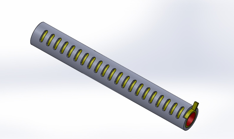
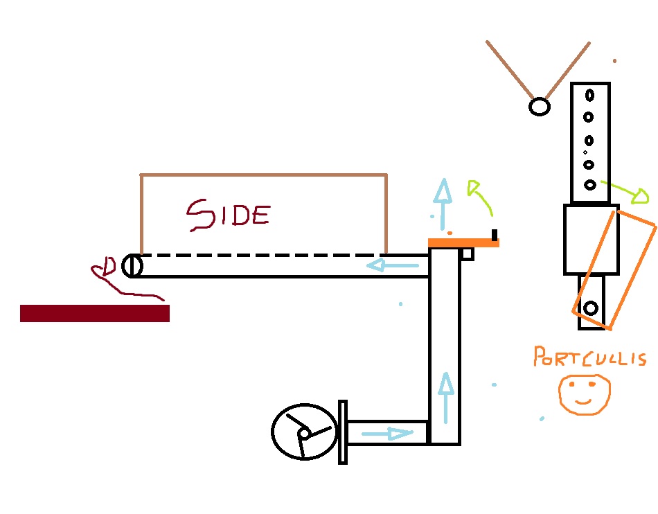
I draw the air valve on my steel table :lol:, basically an aluminum portcullis that drains the flow to the air, with an horizontal knob fast to tune.
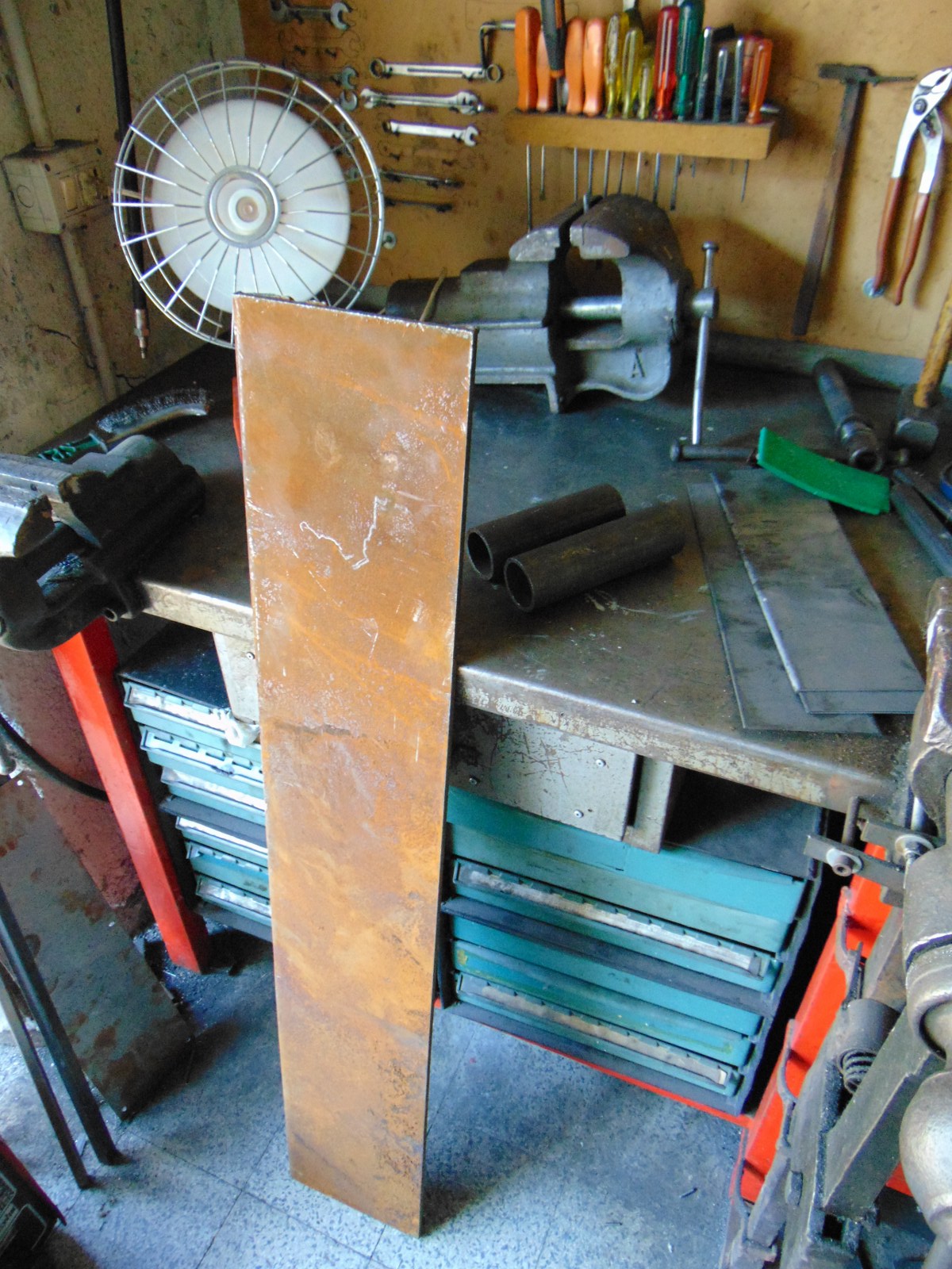
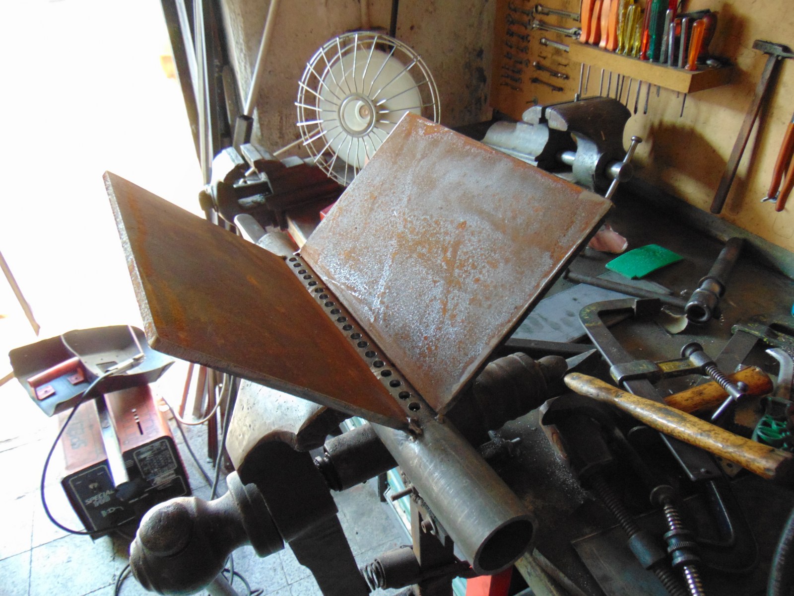
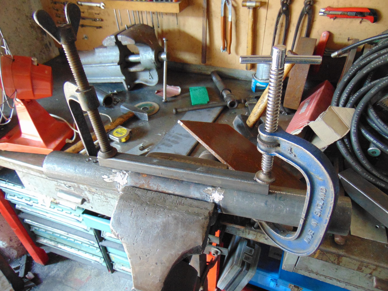
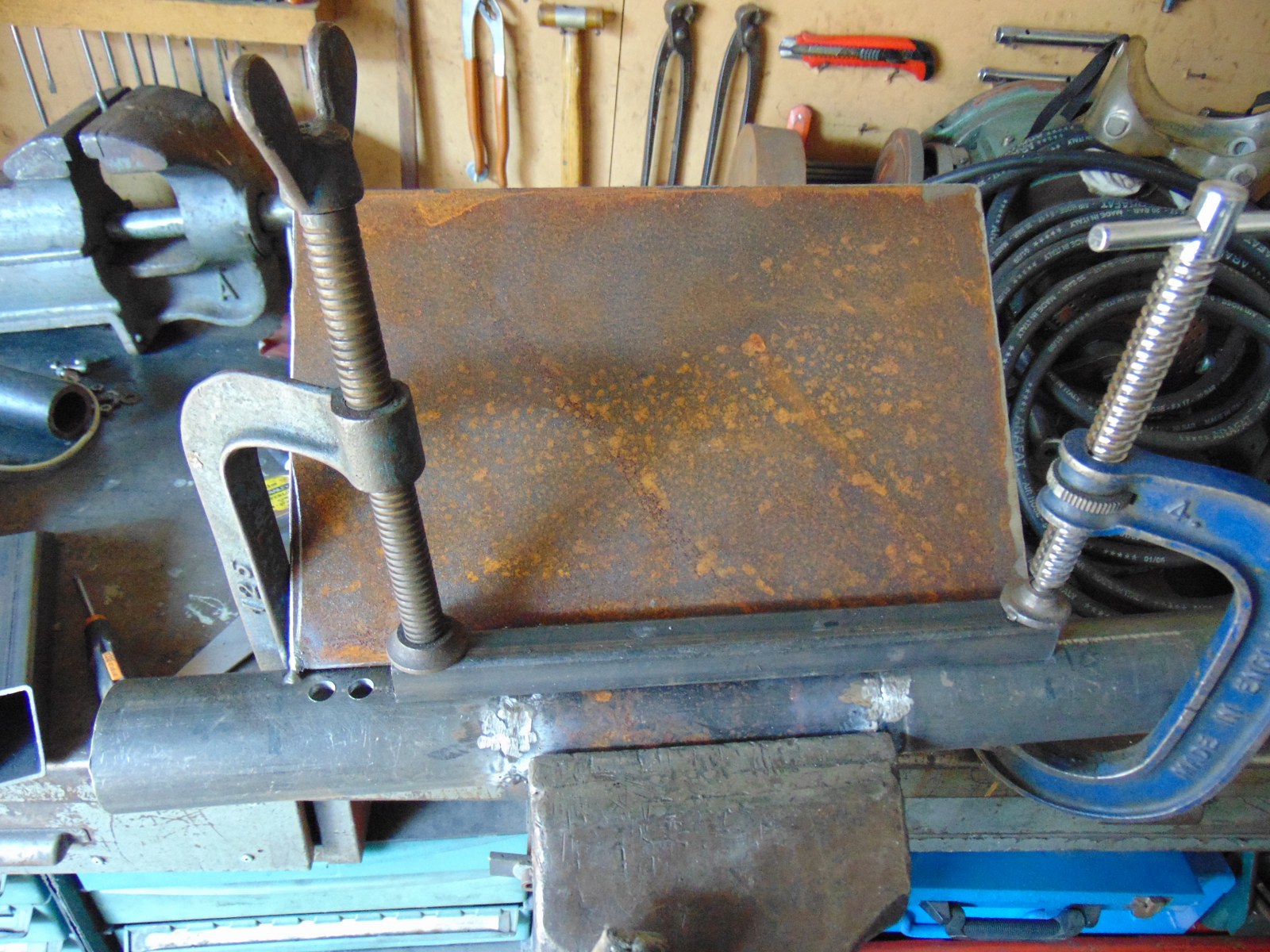
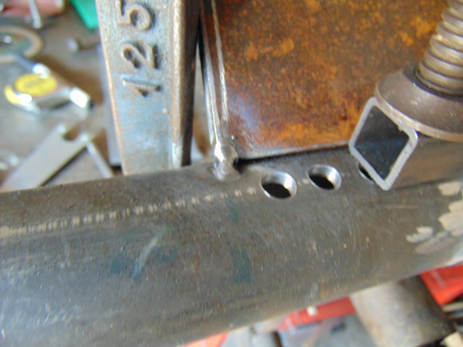
Fireplace lenght is 30cm (12"), 20cm (8") width for the sides, thick 10mm.
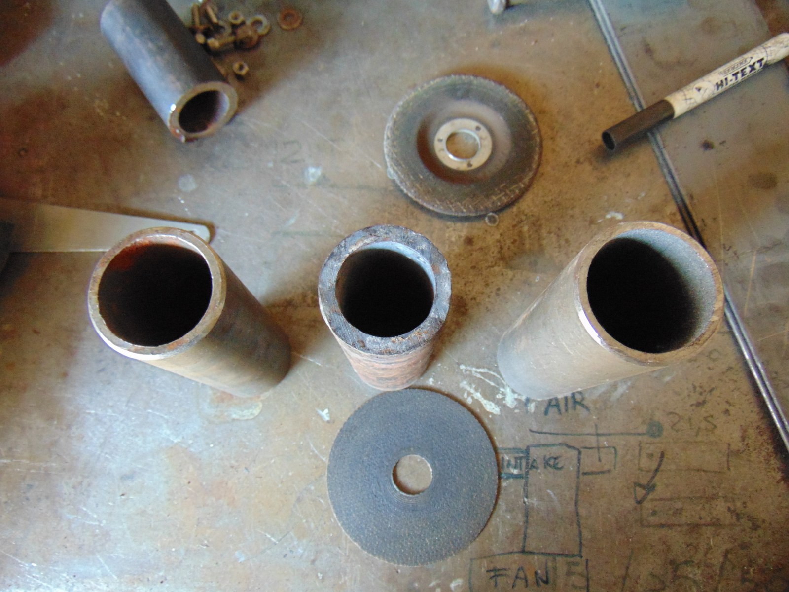
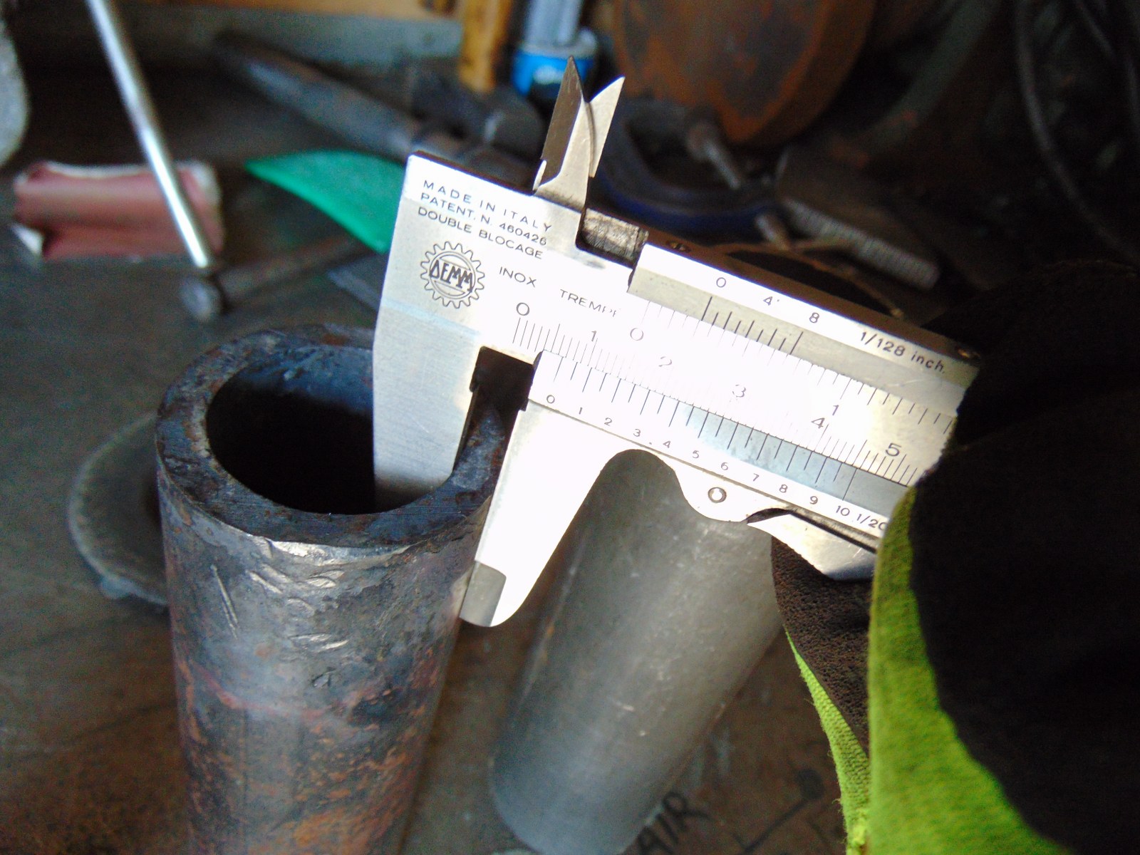
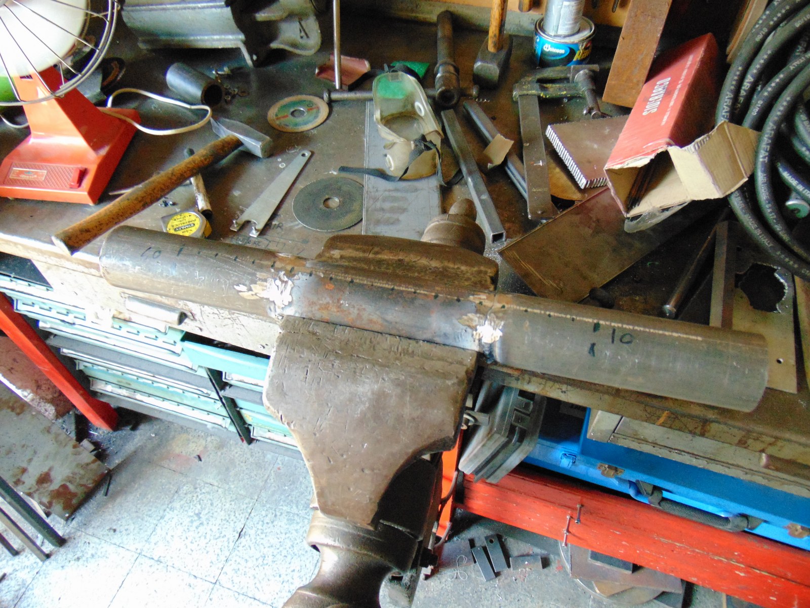
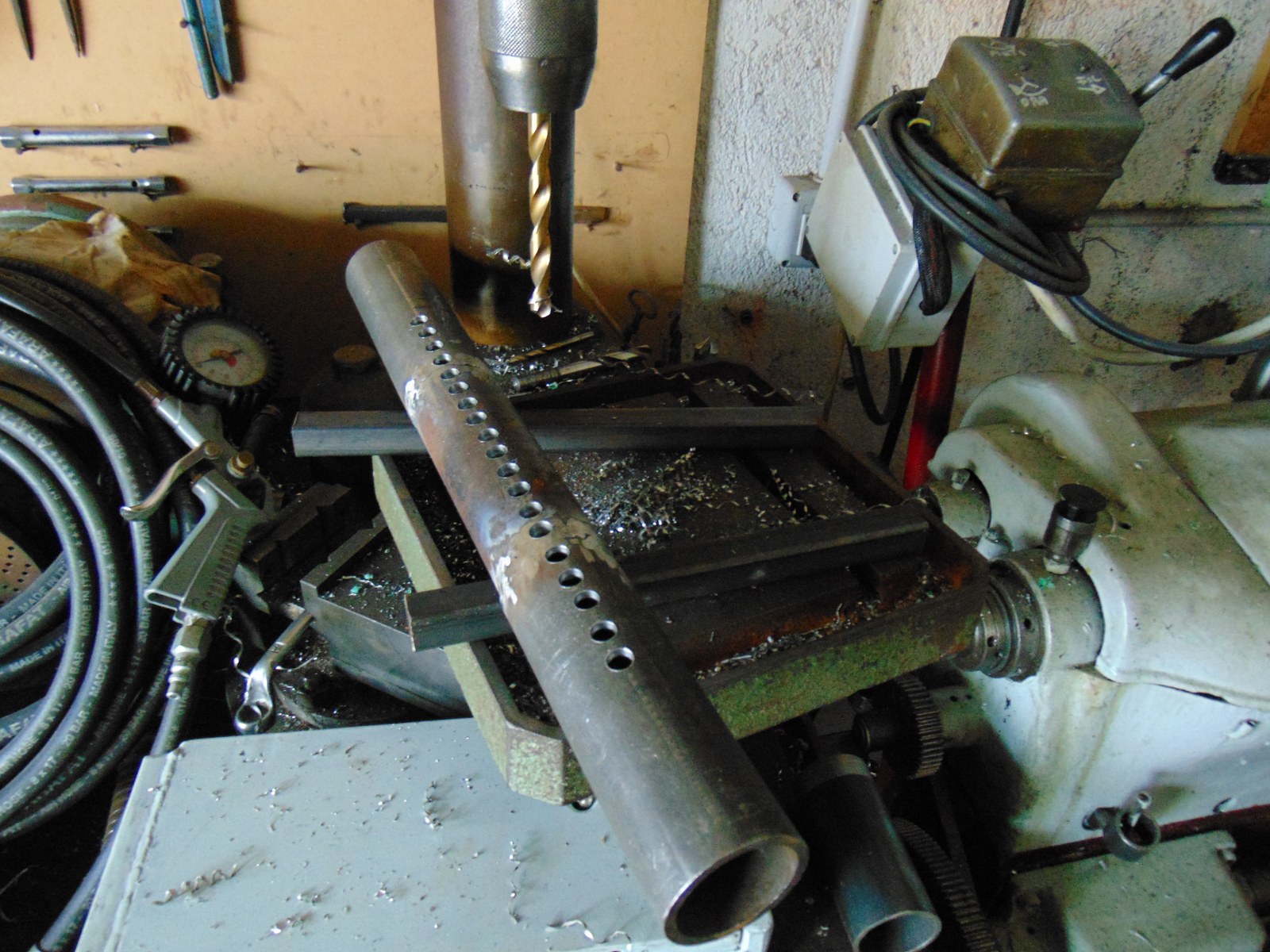
Air intake is composite, the central tube is double thick, about 6,5mm, the zone most used, I think
As usual, stick welding.
Some pictures
Attachment 18577 Attachment 18578 Attachment 18579
Attachment 18580 Attachment 18581
-
As we have a severe shortage of medieval fortresses, first had to reference "portcullis". Then all was clear. So there is no complaint, I think we should enjoy expansion of our vocabulary,
Use of a rod to control fuel exiting the ports is excellent. I suspect your intent is natural gas, using the pattern of the wood fired Vee burners? I suspect Europe supplies gas as we do at about 3/4 [0.75] PSI. You'd need minimal sealing of the rod to tube for control of fuel, it like electricity, seeks an easy exit.
If so, what you've created is a lot like a furnace burner.
Control of fluids and gases are somewhat different, such as gate valves vs ball valves. Gates alter direction internally for pressure and volume, like a faucet. Balls are more like switches, and only appear to control volume. Design intent is on or off. Some use them for coolant on machine tools, we all know how difficult regulating that can be.
It's fun guessing what your next branch of endeavor will be...you've certainly established some epic threads.
-
Hi!
I searched with translator "saracinesca", now Google images shows me the medieval portcullis :lol: ! I'm bad in english, but it was funny!
Pressure of gas in Italy is close to 0,04 bar, you're right, but I don't want to use gas in my forge because it's not practical for my use, it has to be easy to move.
Coal will be the fuel, the tube drilled is only for fresh air coming from the electrofan. I hope I got the size of holes, I got few experience with forge and solid fuels. The gate valve is far from perfection, lot of turbulence and reflections, but at least the flow is controllable due to generous size of the gate.
Unluckily I will have to setup the flux at first power on, maybe I will change the holes, since I really don't know how much air is needed, I have to wait until it's over:rolleyes:
-
Well, if I had to guess; of two tubes 1 inside the other and lengthen your holes [slotted] you could expose open area to regulate flow. A flat on the rod "valve" should do the trick. If fan duct/ manifold is fit with a waste gate, excess cubic flow rate can be vented. I'd bet a simple manometer would show the flow + or - as you adjust. Manometer is just a U of clear poly tube and colored low viscosity fluid like alcohol and dye. If you ever had anything with dual carburetors you'll know the idea. It seems likely more air [controlled] is better than too little. I'm sure those old bellows were close to .63m at maybe 10 pumps per minute.
-
4 Attachment(s)
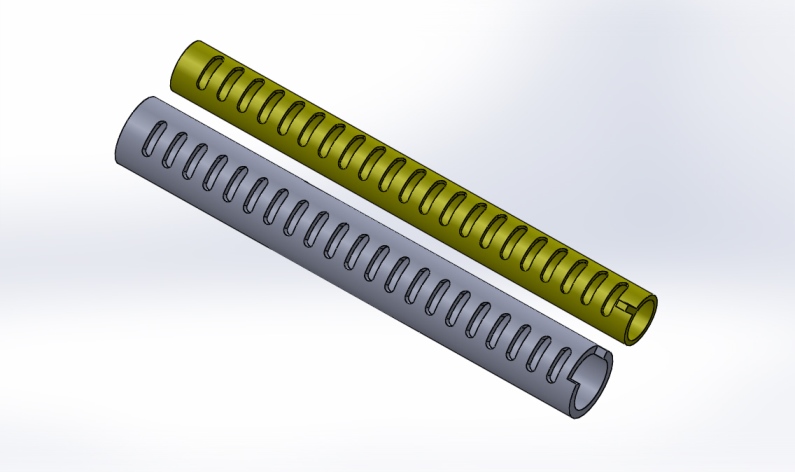
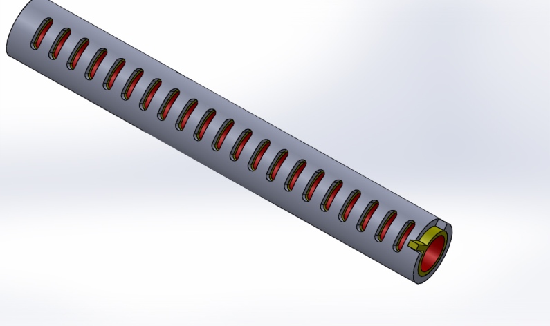
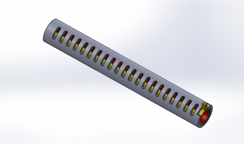
When the need to control air flow in a long forge such as yours I might make this suggestion
make 1 tube to fit inside of the other as it appears that your are doing then instead of having just round holes turn them into slots they will then become a variable venturi allowing for maximum flow to be evenly distributed under the entire length of the fire For the times when you find you only require a smaller shorter fire you could have an additional solid or plugged cylinder inserted from the opposite end of the valve which could be slid in or out like that of a child's Kazoo or it could be open ended and be the supply tube this would require capping one end of the inside tube
Here is a quick design I drew up without a third tube
Attachment 18607 Attachment 18608 Attachment 18609 Attachment 18610
-
6 Attachment(s)
Thanks for the advices!
Frank and Toolmaker you're a great source of good info!
I will keep the advices for a next forge, now I have different internal diameters and a tube plug , for sure, not fits perfect. Certainly it was a very good idea to use this system, making slots and regulate the flow of each part, more the possibility to make a waste gate and check air! It sounds like a well enginereed forge! ...Unfortunately I acted before asking:rolleyes:
Do you think I should dismantle and rebuild?
Attachment 18617
Attachment 18612 Attachment 18613 Attachment 18614
Attachment 18614 Attachment 18615 Attachment 18616
-
I used to race on Friday nights we had a saying back then run with the one that brung ya meaning you ran with what you had or you went home if you did good you know what to expect the next time if not so good you went back and did what ever mods you thought you needed
My main question would be what have you thought of for the ash and clinker clean out?
Having lets call it your portcullis valve elevated above the bottom of the V allowing for ash and clinker to fall to either side to the bottom of the V with a belly door that could be rotated to either side of the open slot where the V would have come together would be my first choice but that would make for a much wider forge and have to be deeper over all
ash needs to have a place to fall out freely so you could slot the sides of the plates similar to how I drew the valve but making them longitudinal adding a matching slotted plate to cover them then you could open and close them having 1 on either side the opening and closing would serve to shear the clinker intl smaller chunks bringing the ash along with it.
But hey its just a thought and I am beginning to think that I might want to build one of my nest forges similar
-
1 Attachment(s)
Sorry for the bad drawing with paint ;)
The end of the drilled tube is opened, the round bar (bordeaux) is sliding so I can enter with a metal brush for cleaning, I hope! The other side is welded or kept with the screws and it's the air intake. I want to put the fan under the forge, at half meter, in order to keep the encumbrances contained
that's more or less the schemati c;)
Attachment 18618
-
I like the design of your tuyere as a whole with the holes in the pipe as you have made it. And upon doing further research not just relying on my own intuition.
Looking at how you are planning on inserting the bordeaux to create a smaller area for when you only need a small flame is much like the drawings I posted sans the bordeaux I believe my design would allow for a much higher air flow but I was reading that it is not always the amount of air but the amount of positive pressure for a given volume. With the rotary type valve the pressure could more easily be regulated with or without a waste gate.
In your design with the waste gate you may be able to achieve the same results only time and fire will tell us
I think though that instead of mounting the blower at the bottom of the tuyere it might be advisable to mount it about half way up and provide an additional clean out at the very bottom
-
Hi rendoman,
A good idea illustrated for a very important adjustment with the gaz heating:agree:
For a portable metal foundry made with forced air combustion I've used drainage(not the right word possibly…)50mm. synthetic -possibly fiberglass but not heat formed - pierced tube as a base and an inner tube with a long slide and a exhaust pipe isolator between the heated part and the plastic one, it was the same principle as yours when it's not necessary to make a big and solid installation as for a forge.
Have a nice day.
Pierre