
 LinkBack URL
 About LinkBacks

Someone suggested I post up some pictures of the CNC conversion I am working with.
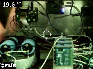
Under the Hood of the control box. This box was built by a friend of mine who started the conversion. I bought the incomplete project and finished it. He helped with the initial setup of servos and encoder dip settings. And started a binder that contains all of the setup info and manuals for all of the components like the servos, breakout board, smoothstepper, encoder settings and so on. Documenting your setup is invaluable when you need to do trouble shooting or look for replacement parts.
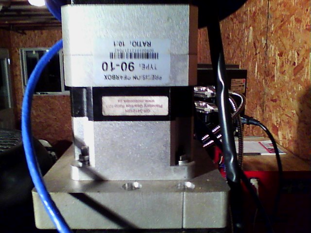
Next we have my Z drive servo. The base block was water jet cut from 1" aluminum plate, then drilled and counter sunk to fit the 10:1 precision planetary reduction box.
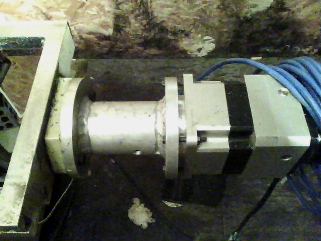
The next is my X table drive. This was made from three pieces of aluminum. The 2" pipe was bored to a snug fit over the bearing housing on the lead screw. The flange plates were counter bored so the tubes slid in 1/4" and were then tig welded. After welding they were finished machined to remove any warping from the welding. The gear reduction on the X&Y are 5:1. The small hole in the side of the tube allow the screws on the couplers to be tightened.
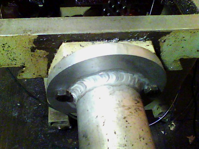
And a close up of the flange and tube that is slid over the lead screw bearing housing. This was done with my Miller 250 Syncro wave.
The Y has exactly the same setup. Servo's are Nema 34's with the Z having a slightly higher rating due to the mass of the gear head it is lifting.


 Reply With Quote

Bookmarks