
 LinkBack URL
 About LinkBacks


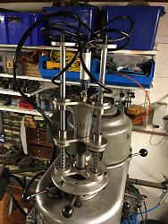
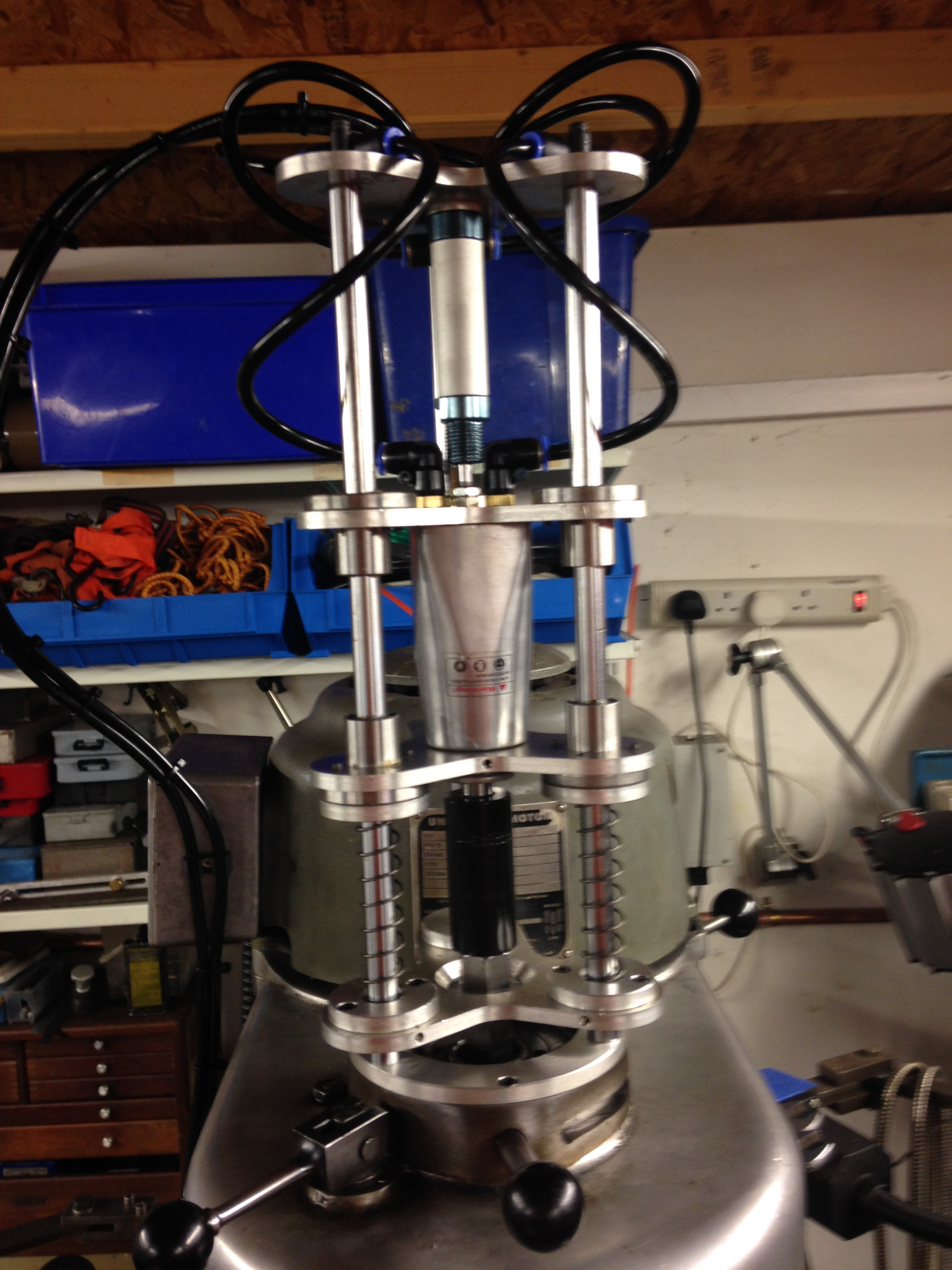
After falling ill, I was struggling to change the tooling on my Bridgeport mill so decided to build a pneumatic power draw-bar. There are plenty of great videos on You Tube and other sites for research, So I decided to try and incorporate all the bits I liked in to this project. This works very well and makes tool changing a lot simpler. Some of the hardware was purchased from eBay air fittings, air hose, cylinder linear bearings and shafts, springs, approximate cost for items £50.00 the rest was manufactured in the workshop.
UPDATE
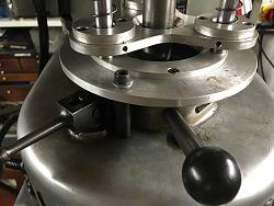
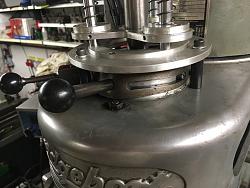
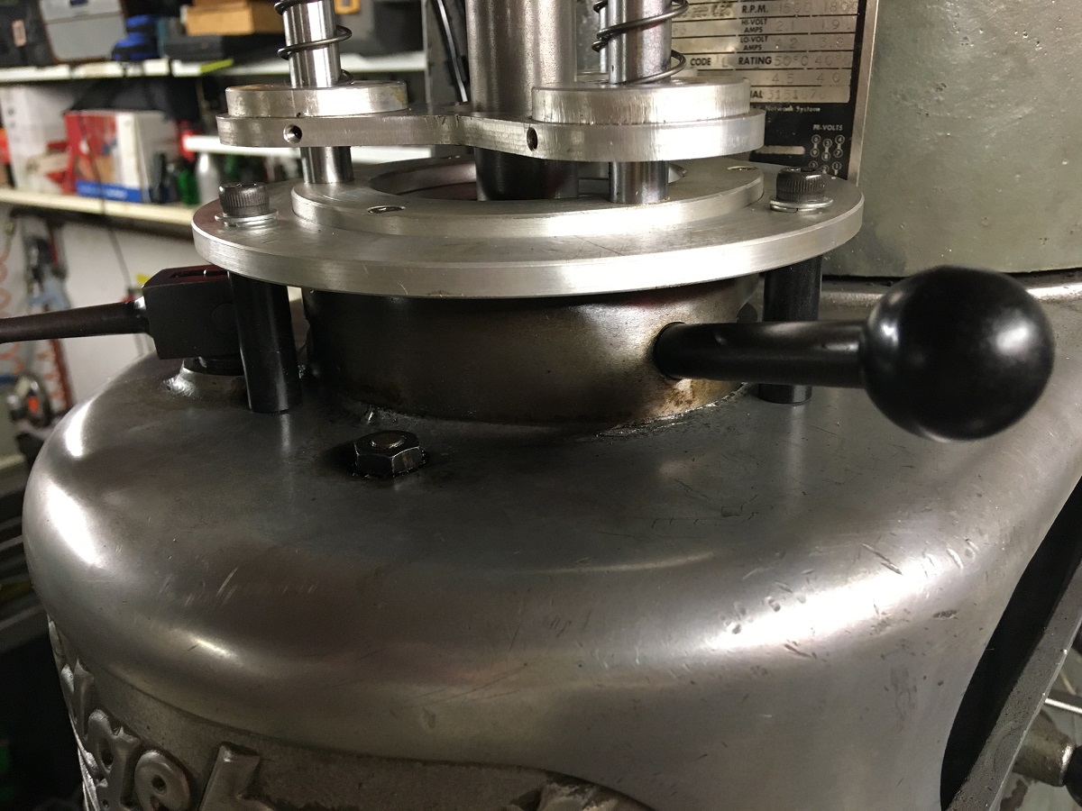
After using power-draw for a few years it occasionally would play up and lift the back-gear lever and jam. I removed it this weekend as I had just had enough with the jamming issue. (doesn't help when you are not well and patients are a bit short) However after 20 minutes of having to manually change the tooling it was definitely the next urgent job to sort and sooner than later. So I have now fixed the power-draw bar directly to the top aluminium casting via three steel stand offs and an aluminium plate machined to suit. This still allows the back-gear and brake lever to operate without any interference from the modification.
Anyone considering building a power draw-bar please don't make the same mistake I made and bolt direct to top casting and not the back-gear castings. As per 1st photo.
The pillars/stand offs are 36mm high and 120 degrees apart on a 136mm Pitch circle diameter (PCD). The first pillar (datum point) is placed equally (by eye) between the brake and back-gear lever. This allows the other pillars to miss nuts etc on the casting top. I used M6 threaded studding, screwed and loctited into the pillars to fit the aluminium top casting and M6 cap screws, plain washer and spring washer to lock the aluminium flange to pillars.
Good luck in your power draw-bar build. One of the best modification I have ever-made. So much easier for tool changing and so quick.
The Home Engineer


 Reply With Quote

Bookmarks