Free 186 More Best Homemade Tools eBook:  
Get 2,000+ tool plans, full site access, and more.

User Tag List

Results 1 to 9 of 9

Thread: Questions about wiring a 115v single phase Baldor motor

  1. #1
    Supporting Member tmate3's Avatar
    Join Date
    Jan 2021
    Posts
    110
    Thanks
    9
    Thanked 251 Times in 63 Posts

    tmate3's Tools

    Questions about wiring a 115v single phase Baldor motor

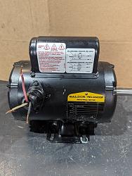
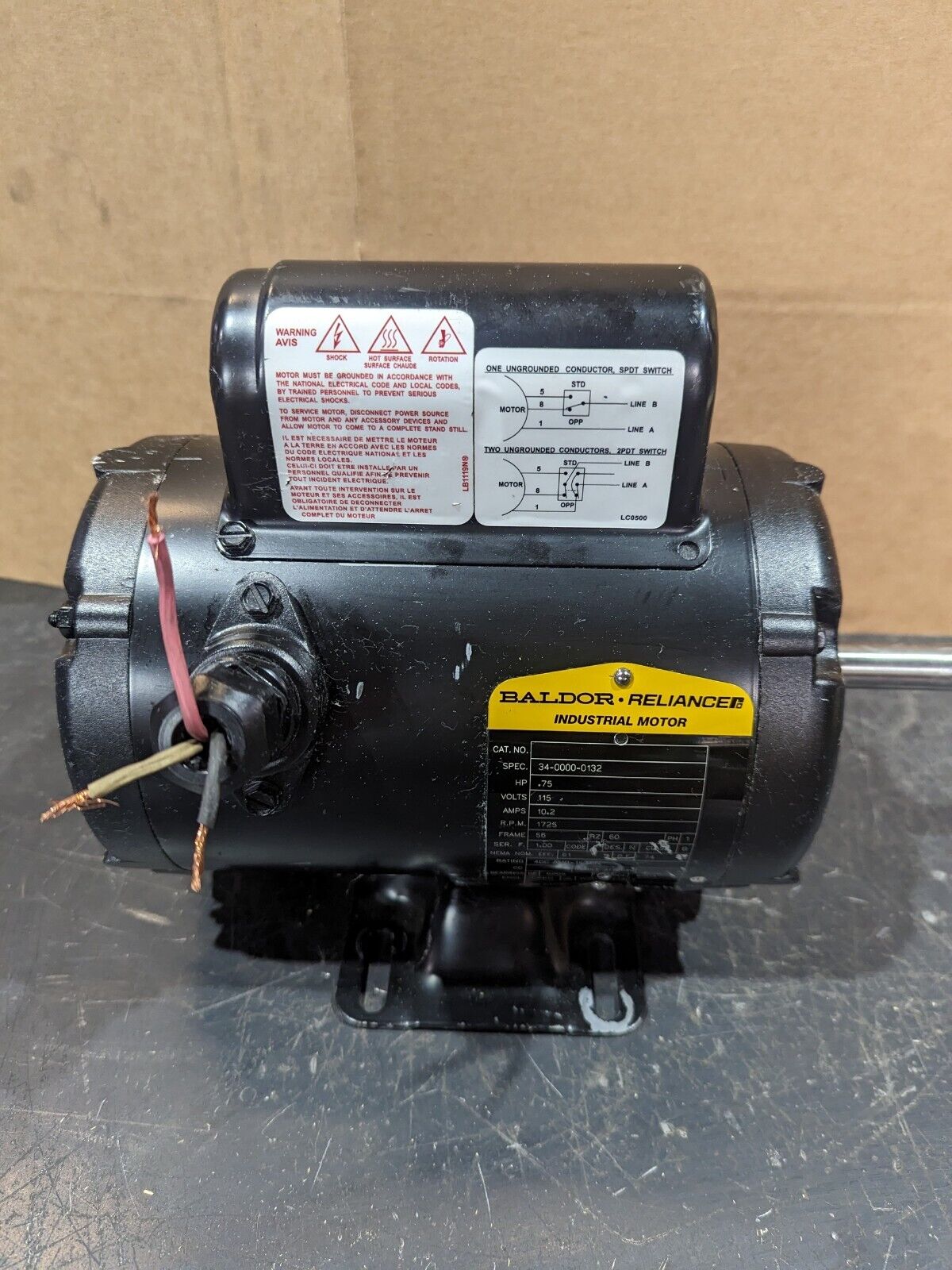
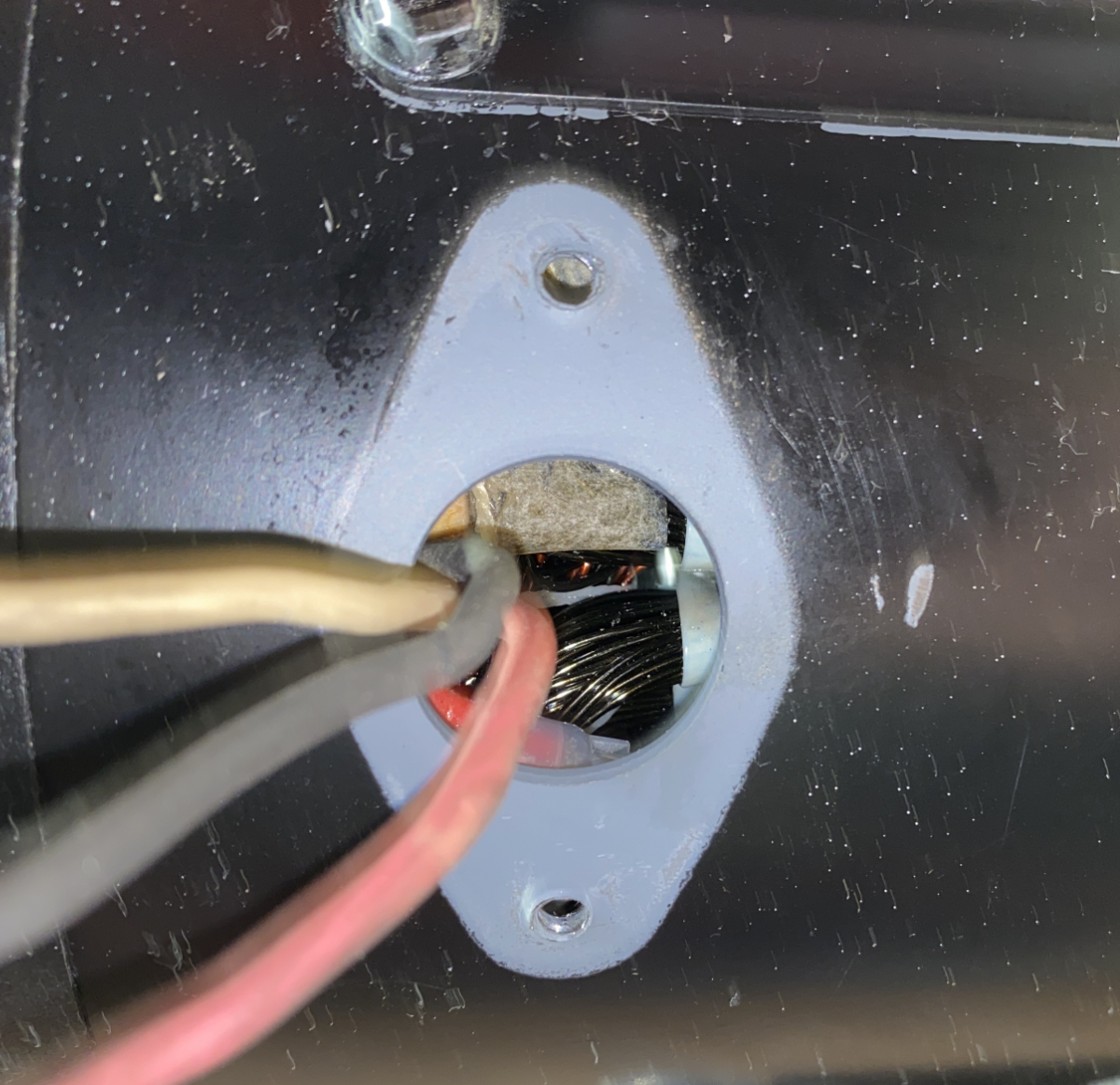
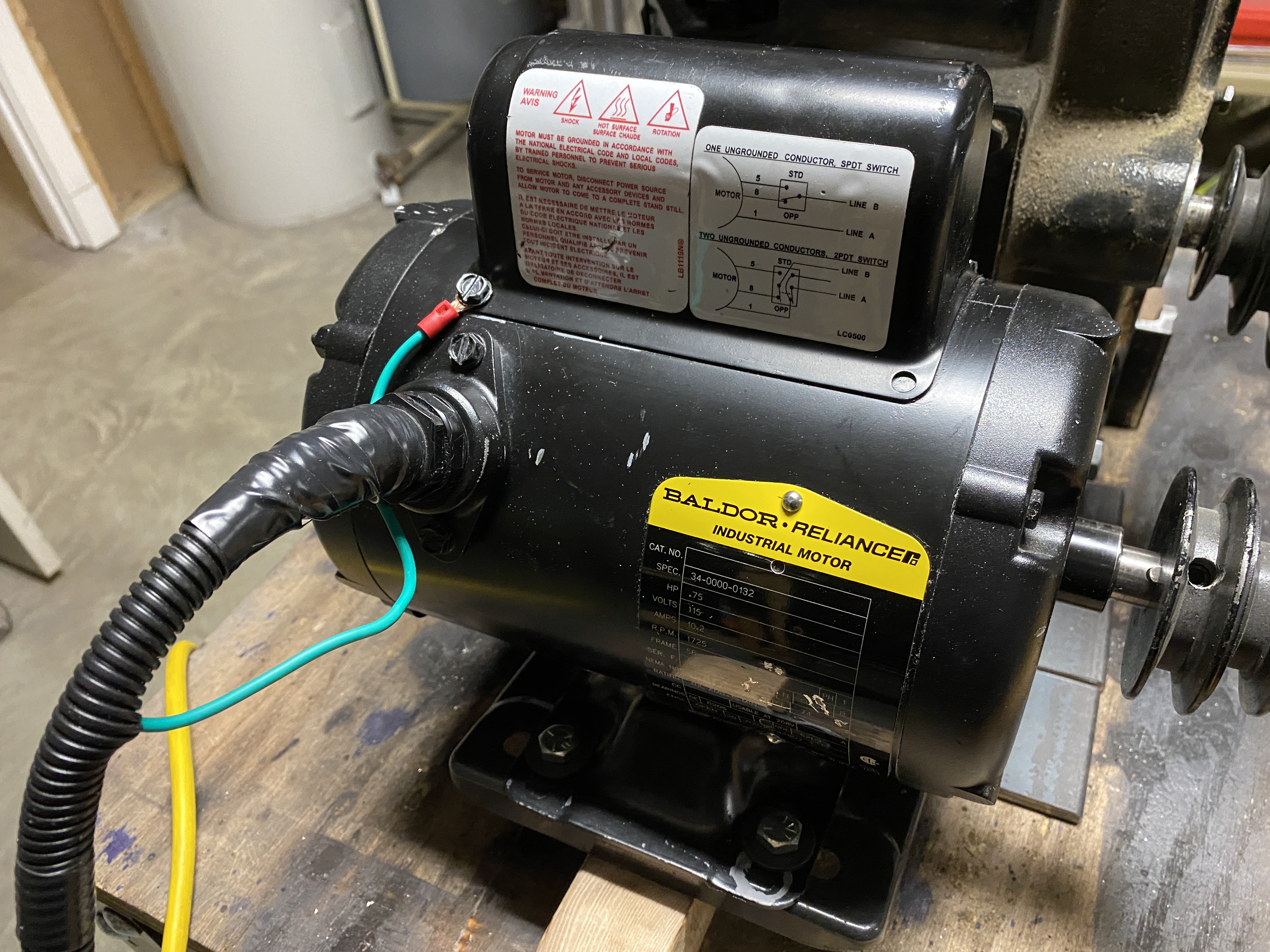
    I just purchased a 3/4 hp single phase Baldor motor on eBay, which hasn't arrived yet. I need it to rotate counter clockwise when looking at the shaft end. There are three wires sticking out of the motor - green, red, and white. I understand that the green is ground, and it doesn't matter which way the other two connect to the two remaining plug terminals.

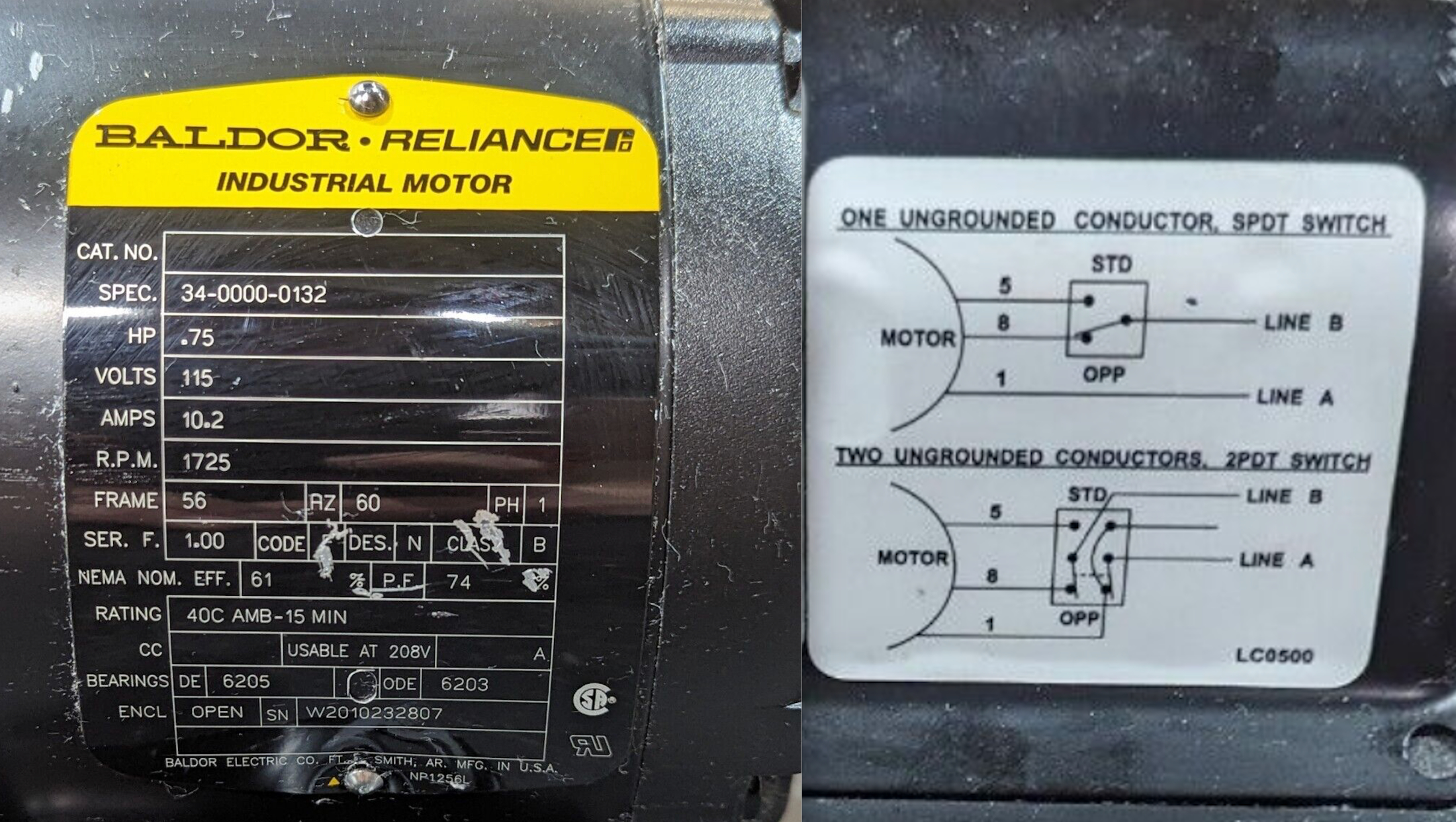
    The wiring schematic on the motor shows how to reverse the direction, if necessary, but I'm not sure I know how to interpret it. I think Std means clockwise, and Opp means counter-clockwise, but when viewed from which end of the motor? Which diagram do I use to reverse the rotation? The top diagram seems simple enough, but the bottom diagram not so much.

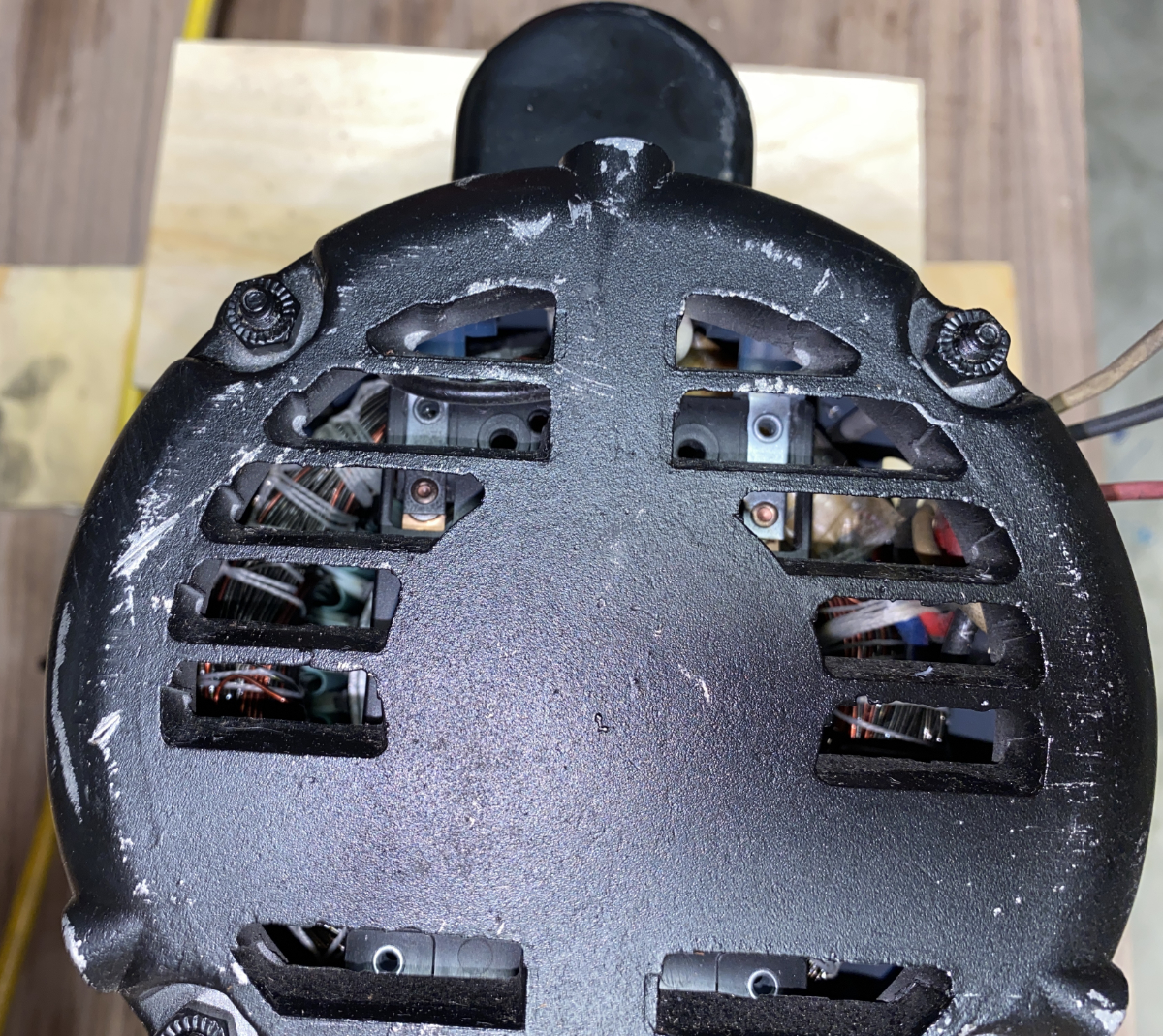
    Also, what is the best way to deal with the three wires sticking out of the motor? I'm thinking I should pull off the plastic/nylon connector and wires, and attach the new cord to wherever the old wires were attached.

    Questions about wiring a 115v single phase Baldor motor-baldor-motor.jpg Questions about wiring a 115v single phase Baldor motor-baldor.jpg

    186 More Best Homemade Tools eBook

  2. The Following 3 Users Say Thank You to tmate3 For This Useful Post:

    bob_3000 (Feb 24, 2023), nova_robotics (Feb 24, 2023), rlm98253 (Feb 24, 2023)

  3. #2
    Supporting Member
    Join Date
    Dec 2022
    Location
    Midwest US
    Posts
    249
    Thanks
    176
    Thanked 144 Times in 97 Posts

    ductape's Tools
    The schematics show how to wire it to different types of switches in order to be able to change rotation direction as needed. Connect the neutral to line 1 and the ground to the frame or ground wire. Connect the hot to line 5 for clockwise, or line 8 for counterclockwise. Rotation is as viewed from the exposed shaft end. Cap the unused wire with a wire nut and tape.


    Ignore the wires sticking out of it. The wires marked with the numbers should be either under the bolted part of the connector assembly on the side or under the rounded cover on top.


    In addition, you can put the spec number shown on the plate into the search field of Baldor's web site and get a lot of technical information about it.

    2000 Tool Plans

  4. The Following 3 Users Say Thank You to ductape For This Useful Post:

    bob_3000 (Feb 24, 2023), nova_robotics (Feb 24, 2023), rlm98253 (Feb 24, 2023)

  5. #3
    Supporting Member BuffaloJohn's Avatar
    Join Date
    Aug 2019
    Location
    Oregon, USA
    Posts
    635
    Thanks
    244
    Thanked 321 Times in 195 Posts

    BuffaloJohn's Tools
    On https://www.baldor.com/catalog/34-0000-0132 you will find a drawing CD0088.

  6. #4
    Supporting Member tmate3's Avatar
    Join Date
    Jan 2021
    Posts
    110
    Thanks
    9
    Thanked 251 Times in 63 Posts

    tmate3's Tools
    The motor came today. I pulled the wiring connector, and the three wires just disappear into the casing, and don't pull out any further than they are. If I look into the end of the motor, I can see a couple of connections, but not what wire is connected to what. I can't imagine Baldor requiring you to take the end of the motor off to change rotation direction.


    The wiring diagram shows the rotation direction being dependent on whether the red (8) or black wire (5) goes to line B. It would seem that if I connect the white wire to one terminal on a plug, and either the black or red wire to the other, the motor would work. But if that's the case, how would I hook up the ground terminal on the plug?

    Questions about wiring a 115v single phase Baldor motor-wires-into-motor.jpg Questions about wiring a 115v single phase Baldor motor-end-view.jpg

  7. #5
    Supporting Member BuffaloJohn's Avatar
    Join Date
    Aug 2019
    Location
    Oregon, USA
    Posts
    635
    Thanks
    244
    Thanked 321 Times in 195 Posts

    BuffaloJohn's Tools
    Quote Originally Posted by tmate3 View Post
    how would I hook up the ground terminal on the plug?

    Click image for larger version. 

Name:	wires into motor.jpg 
Views:	53 
Size:	901.9 KB 
ID:	45021 Click image for larger version. 

Name:	end view.jpg 
Views:	58 
Size:	1.42 MB 
ID:	45022
    Find some bare metal screw and attach there. Longer term, ground the mounting bolts to the motor. It looks like the motor might be fully isolated from the case, so you can think more about where to ground once you mount it...

  8. #6
    Supporting Member tmate3's Avatar
    Join Date
    Jan 2021
    Posts
    110
    Thanks
    9
    Thanked 251 Times in 63 Posts

    tmate3's Tools
    I wired it up temporarily to an extension cord with the receptacle end cut off. I connected white to white, red from motor to black from cord, and a wire from a screw on the motor case to the green on the cord. It ran perfectly counter-clockwise, which is what I wanted. The only remaining question since I can't get to the wire connections in the motor, is what is the best way to safely connect the three 2" long wires from the motor to a cord?

  9. #7
    Supporting Member BuffaloJohn's Avatar
    Join Date
    Aug 2019
    Location
    Oregon, USA
    Posts
    635
    Thanks
    244
    Thanked 321 Times in 195 Posts

    BuffaloJohn's Tools
    mount a small box over the place where the wires come out, using the screw holes already there, that is what I would do...

  10. The Following User Says Thank You to BuffaloJohn For This Useful Post:

    ductape (Feb 25, 2023)

  11. #8
    Supporting Member
    Join Date
    Dec 2022
    Location
    Midwest US
    Posts
    249
    Thanks
    176
    Thanked 144 Times in 97 Posts

    ductape's Tools
    The box idea is a good one, especially since there are already existing threaded holes for mounting. Other options are a couple layers of shrink tubing after soldering the wires, or crimp connectors with shrink tube. Both will hold reasonably well as long as the cord isn't being pulled on when the motor is mounted.

  12. #9
    Supporting Member tmate3's Avatar
    Join Date
    Jan 2021
    Posts
    110
    Thanks
    9
    Thanked 251 Times in 63 Posts

    tmate3's Tools
    It's all wired up now, and works perfectly. Thank you all!

    Questions about wiring a 115v single phase Baldor motor-img_4692.jpg


    186 More Best Homemade Tools eBook

Thread Information

Users Browsing this Thread

There are currently 1 users browsing this thread. (0 members and 1 guests)

Bookmarks

Posting Permissions

  • You may not post new threads
  • You may not post replies
  • You may not post attachments
  • You may not edit your posts
  •