 LinkBack URL
 About LinkBacks
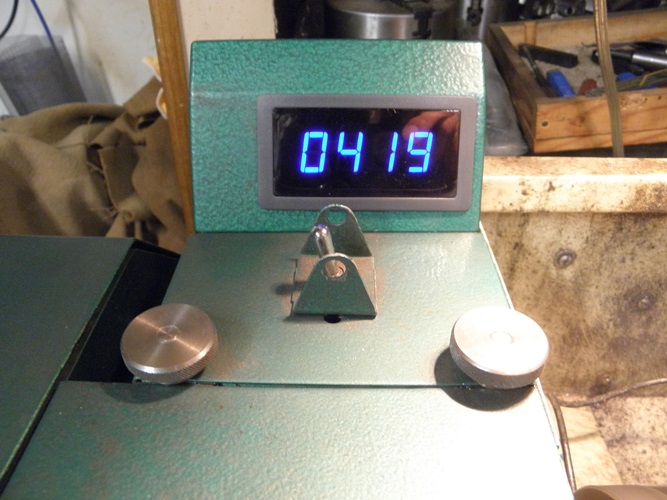
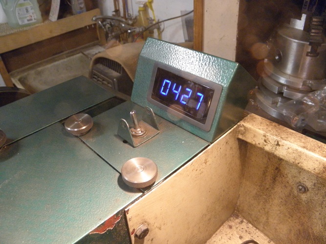
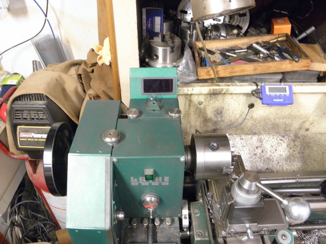
R.P.M Lathe meter mod. New blue meter mod.


R.P.M Lathe meter mod. New blue meter mod.
baja (Mar 11, 2021), ColWA (Feb 17, 2019), davidschutt (Dec 6, 2024), FEM2008 (Mar 10, 2021), high-side (Feb 11, 2019), Jon (Feb 12, 2019), Ken Koch (Feb 12, 2019), odd one (Mar 10, 2021), Paul Jones (Feb 9, 2019), PJs (Feb 13, 2019), rossbotics (Feb 10, 2019), Tonyg (Feb 12, 2019), Toolmaker51 (Feb 11, 2019), Tule (Feb 12, 2019), UncleBob (Feb 17, 2019)
There are currently 1 users browsing this thread. (0 members and 1 guests)
 Posting Permissions


 Reply With Quote
Bookmarks