Rotary Broaching a Keyway on the Lathe with simple materials you probably have in the shop.
Also my FIrst Video on the New Channel :cool:
https://youtu.be/Yi9J3kRKdBM
Rotary Broaching a Keyway on the Lathe with simple materials you probably have in the shop.
Also my FIrst Video on the New Channel :cool:
https://youtu.be/Yi9J3kRKdBM
<!-- BEGIN /var/www/html/homemadetools/protected/modules/zeus/views/tool/postUpdate.php -->
Thanks JRock! We've added your Rotary Broaching Tool to our Lathe Accessories category,
as well as to your builder page: JRock's Homemade Tools. Your receipt:
<div id="blocks"> <div class="block b1 pngfix"> <div class="bimg"> <div> <a href="https://www.homemadetools.net/homemade-rotary-broaching-tool-5"> <img src="/uploads/229433/homemade-rotary-broaching-tool-5.jpeg"/> </a> </div> </div> <div class="head pngfix"></div> <div class="left pngfix"></div> <div class="right pngfix"></div> <div class="blockover b1 pngfix"> <div class="title"> <a href="https://www.homemadetools.net/homemade-rotary-broaching-tool-5">Rotary Broaching Tool</a> <span> by <a href="https://www.homemadetools.net/builder/JRock">JRock</a></span> </div> <div class="tags">tags: <a href='https://www.homemadetools.net/tag/lathe'>lathe</a>, <a href='https://www.homemadetools.net/tag/broach'>broach</a> </div> </div> </div> </div>
<!-- END /var/www/html/homemadetools/protected/modules/zeus/views/tool/postUpdate.php -->
Awesome! Thanks!
Hi JRock
I am not great at making videos myself but I would like to give you some feedback as a watcher of this video.
When talking and having the lathe motor running made it difficult to hear you explain what you were doing. Also it would helpful for those that haven’t tried rotary broaching to have an explanation on the angle of the tool entry to work piece and how the wobble of the tool cuts as it passes through the component being machined. Rotary broaching is quite difficult to get your head around if you have never seen the cutters small movement while both the tool and work piece rotate. I thank you for posting as this is a very interesting subject with many uses and very difficult in my opinion to explain how the process works.
I look forward to seeing more of your videos and no offence is intended with the feedback.
The Home Engineer
THanks. I appreciate the constructive feedback. Yeah, that's my pullstart 3PH converter running pretty close to the camera. Unfortunately it's the best place to get a nice shot for the lathe work. I'll get around to enclosing it one of these days. I figured there's already a bunch of explanations on how it works by people far more eloquent than myself (TOT and AVE both have great videos on it). I might end up making another one for my 1" Arbors, and I could go through some of that. great idea.
Hi JRonk’s
Rotary broaching is a fascinating subject and is amazing how it works. Looks like you have a nice setup so looking forward to more posts from your shop.
The Home Engineer
Yeah it is. I was just explaining on FB today, that this particular incarnation is not transferrable to a milling machine with a stationary workpiece, and it bent my brain a hair picturing why not.
The bearing would have to be offset in the bar to get it to wobble properly.
How much? Somewhere between a skosh and a bit :lol:
That's one of the nice things, so far as I can tell, and for my purposes, it doesn't need to be precision.
There's probably optimal settings, and some sort of formula that could be figured, but it doesn't seem critical.
It is possible to do on a mill. The spindle obviously rotates and the tool and workpiece both stay stationary. (I say the tool stays stationary!) The tool holder has a chuck type holder but the tool shaft is set in bearings so the spindle rotates but the tool doesn’t (due to tool shaft in bearings) The tool shaft is not at 90 degrees to the main spindle and is at an angle no bigger than a degree. As the spindle rotates the tool is forced to move back and forth and with applied pressure from the mill quill or raising the mill table allows the tool to broach the desired form of the tool while not rotating but more of an oscillating action being used. The tool bit is ground with clearance on the side and slightly dished at the bottom to create clearance and a clean sharp cutting edge. The cutting tool does require a hole the same size or bigger than the A/F of the cutting tool (if cutting squares, hexagons etc) or in the case of a keyway the tool holder would be supported by the bore but would need to be able to move in the bore to allow the cutting tool to move in the same oscillating movement to cut. This could be achieved by having a bead radius on the end of the tool holder the same size of the bore but allowing the tool holder to mov. (I have never cut a keyway using this method hence the interest in your video and post) I will see if I can find a video of the cutting action and post on HMT
I hope this makes sense and would be very interested in your views and others. Just incase I am totally barking up the wrong tree.
The Home Engineer
https://youtu.be/C5i6WteJ2wU
please note I am not connected to this company but this shows the movement of the cutting tool as it cuts. I hope this supports my long winded previous post
It can be done in a mill, just not in the configuration I use in my video.
It'd be as simple as offsetting the bearing / center from the center an 1/8" or so.
The bar would turn and wobble the tool in the stationary workpiece.
Those tools with the double bearings are lovely, but it doesn't have to be that complicated to get the job done.
Yeah, the ability to cut a keyway without a bunch of extra, expensive tools (or breaking my butt) is what got my fire lit :)
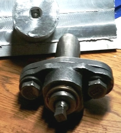
Attachment 33376
Here's mine that I made from an adjustable tool holder from Ebay. The cutting tool is a 1/4" lathe tool shaped to cut on the end and it makes 1/4" square holes. The front cap flange of the tool holder has been machined 1º off of perpendicular and installed shoved all the way to the outside of its adjustment range, and if a rod is inserted into the bronze bearing cup and the assembly rotated in a lathe chuck the rod appears to make an X shape in the air. The tool is cutoff so that its cutting edge is located as close as I can get it to the crossover of the X seen before.
When chucked in either the mill or the lathe, as the chuck rotates one angular position is a little closer to the work than all the rest so as that position comes to each corner it pushes the tool a little deeper into the work and by successively cutting each corner the square hole progresses into the work. At some point, determined by the relief ground into the tool, the tool shank begins contacting the entry hole and so it can progress no further into the work. That's why you see commercially made tools with long reliefs ground into them so that the tool can go deeper but it's also taking significant meat from the tool core making it weaker.
It takes a lot of force from the machine and a generous amount of lube is required but the broaching goes surprisingly fast at high spindle rpms. The operation leaves inward turned flower petal looking chips in the hole and those are easily broken out with a pointed tool later. I made a steel carrier for that tool which the cup bearing rotates around and if I want a different size hole then I have to make a carrier for that different sized tool, but so far making 1/4" square holes deep enough to get a ratchet into has been enough for me.
Is that a turret tool? I think I have a couple of them around, wondering what I'd do with'em. That's great!.
Love to see the guts.
I think it originally was. They can still be found on Ebay for a reasonable price and it saved me a bunch of work.
It's really dirt simple. I just flycut a 1º off perpendicular surface along the long axis of the tool holder cap flange, then machined a bronze cup bearing with a top flange that fits the tool holder cap bore and a similar looking tool carrier out of steel which fits the cup and is bored to hold the square lathe tool by its corners. The bearing is only as long as the tool holder cap is deep and the tool carrier doesn't quite bottom out in the bearing so that the broaching force is felt by the bearing flange and the carrier flange.
The slickest part of the build for me was chucking the lathe tool in the 4 jaw and then mounting a Dremel with a cutoff wheel onto my tool post and when it was brought edge on against the spinning work it ground a nice hemispherical depression in the end of the lathe tool to provide rake for the cutting edges. It looked like it was done in an actual machine shop.
Good luck in your search for where you put those tool holders. :cool:
Very cool. That CutOff wheel is a great idea.
I know exactly, approximately, which pile it's in :lol:
You just think you know which pile. I'd bet a mustard covered donut that it'll eventually be found elsewhere. That's how it goes here - I'm about to order another pair of vice grips because I can't find mine and I've looked everywhere 3 times (everywhere except where they are).
:lol: You'll find'em shortly after the new ones arrive!