
 LinkBack URL
 About LinkBacks


Hi All
Yesterday I spent the day making a new worm shaft for my rotary table. The reason for this, I am currently trying to make this motorised. controlled via an Arduino and stepper motor. As I need to find away of coupling the shaft of the rotary table to the stepper motor I didn't want to make modification to the existing shaft just in case I ever need to convert back to manual table.
The last time I cut a worm was in my apprentice days so a bit of head scratchingand research it all came flooding back.
The first thing was to remove the existing shaft so I could get some measurements. As I could measure the pitch this was a good starting point and the table being made in Spain I was guessing it would be a Module gear? so to calculate the Mod=Pitch/Pi. So Mod=6,28/3.14= Mod 2,
I then calculated the helix angle to ensure I had enough lead clearance when setting the tool and cutter to cut the HSS tool. The helix angle is simple trigonometry. First the opposite side is the pitch and the adjacent side = (Pi x Dia of shaft) which equates to one full thread.
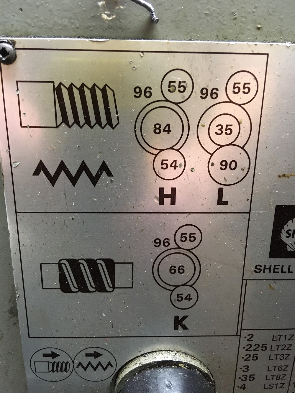
The shaft blank was machined and the lathe gear box/gear train set to the Mod 2 mode.
Gear selection chart
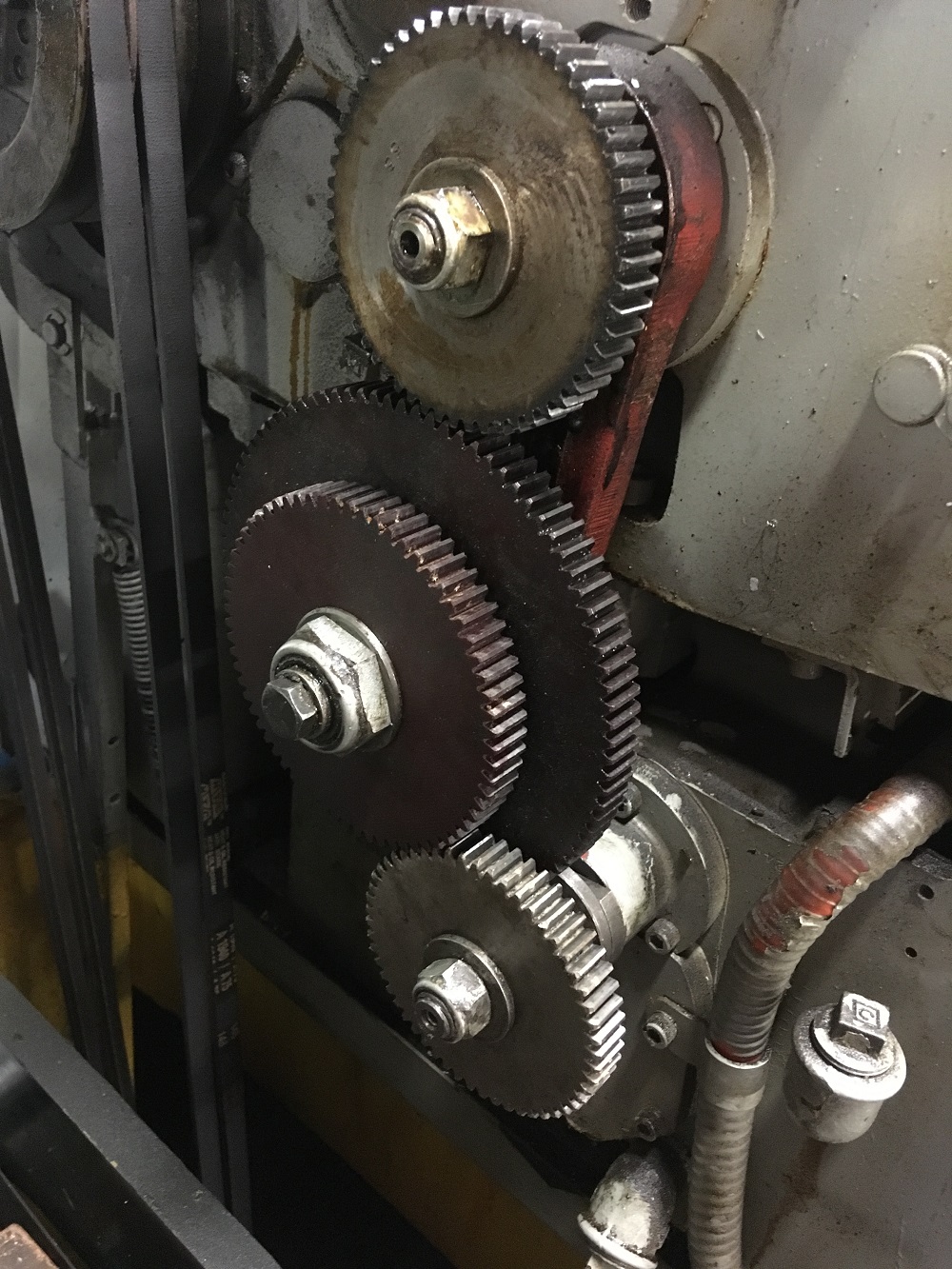
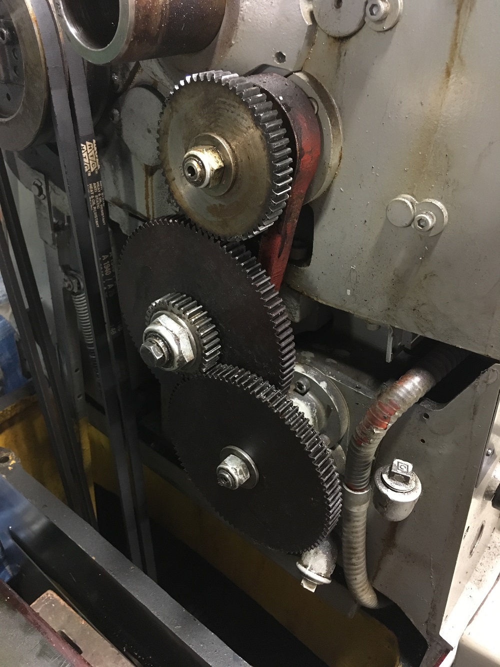
Mod gear train
Standard low range gear train I normally use
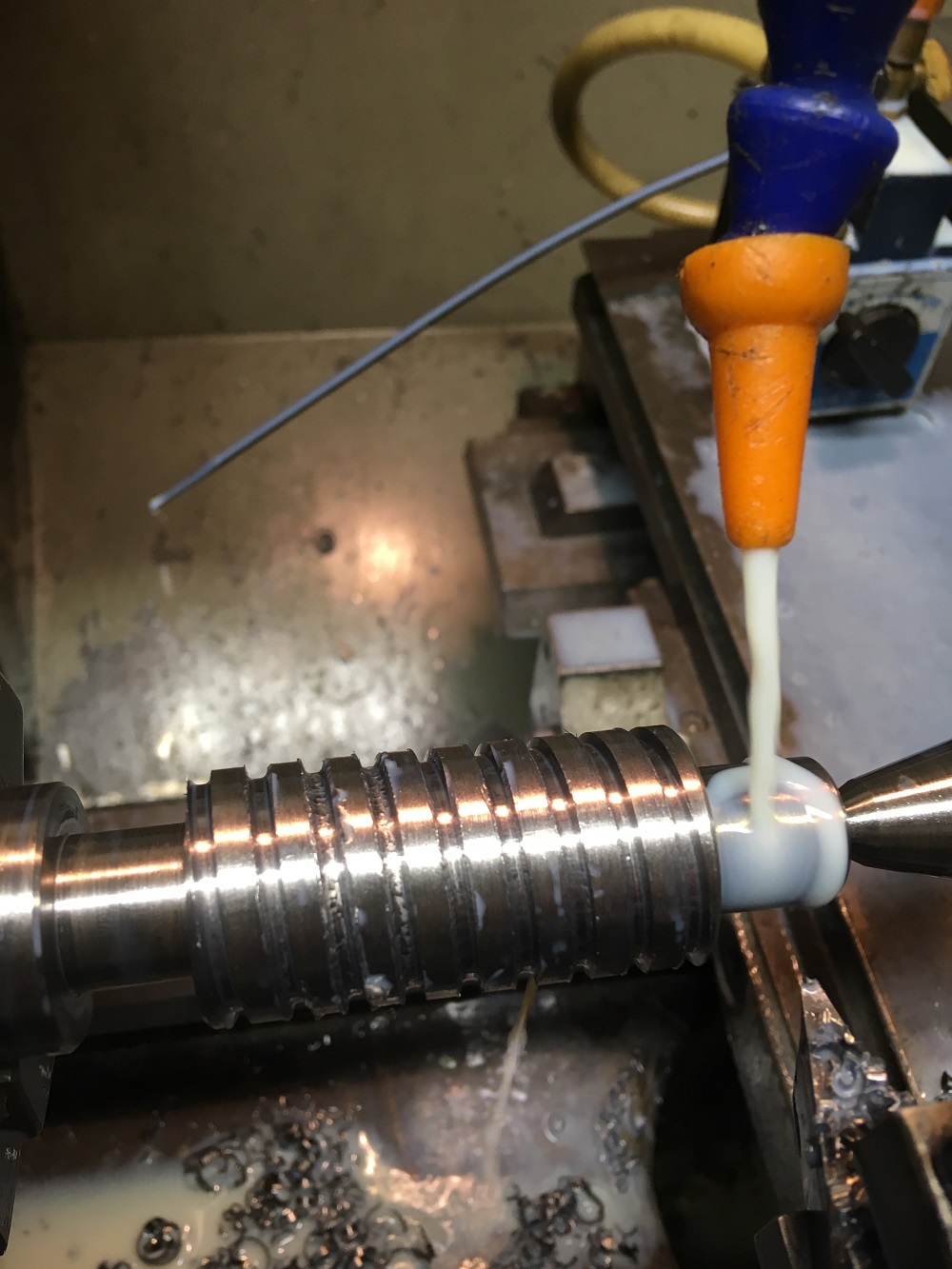
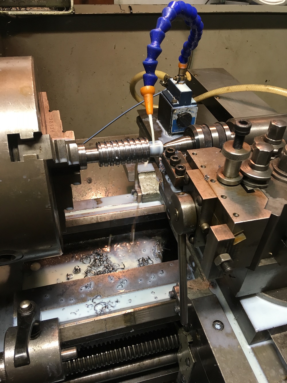
First few passes.
Retracting tool makes the process a lot easier
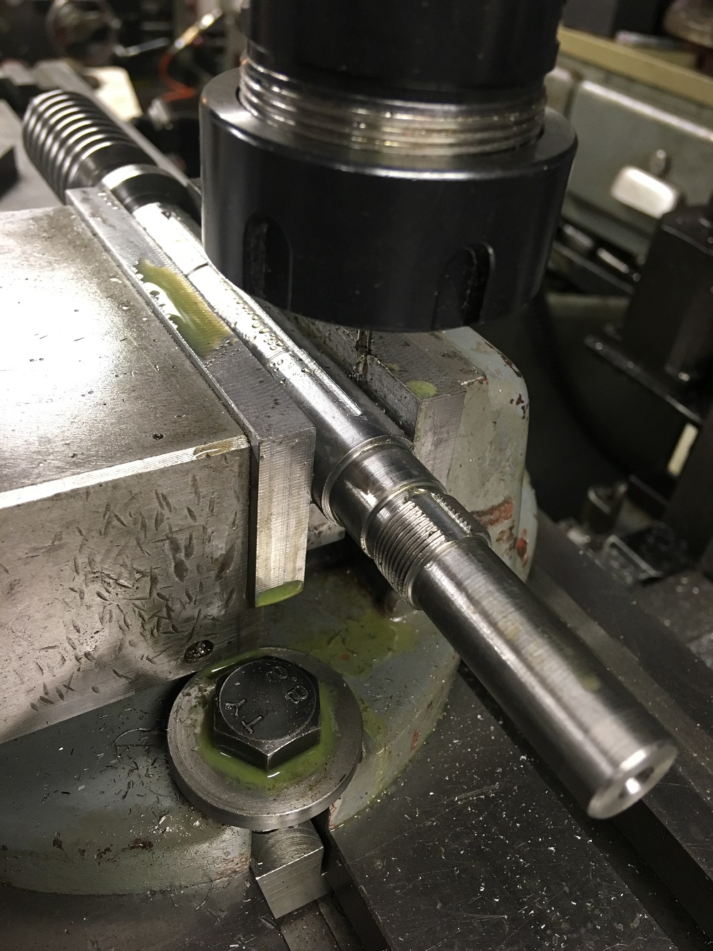
Milling oilway and lock washer tab slot
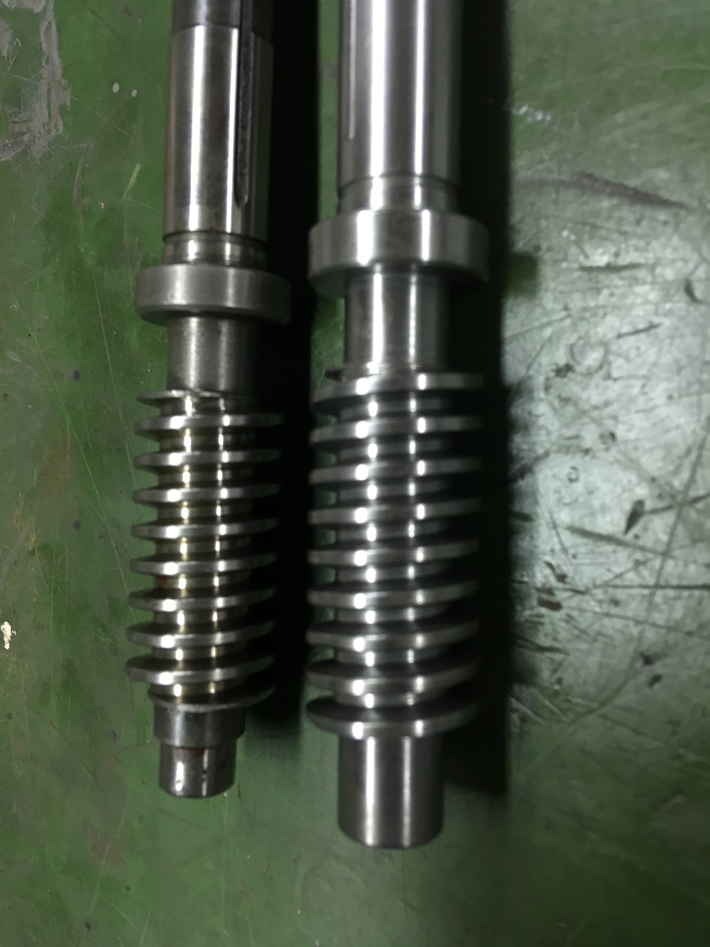
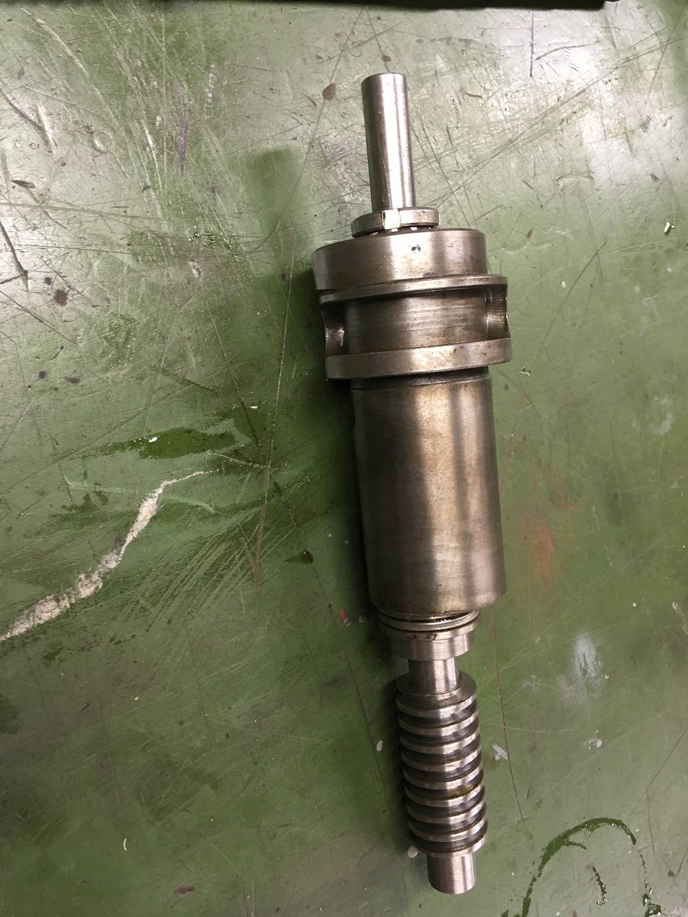
Finished worm
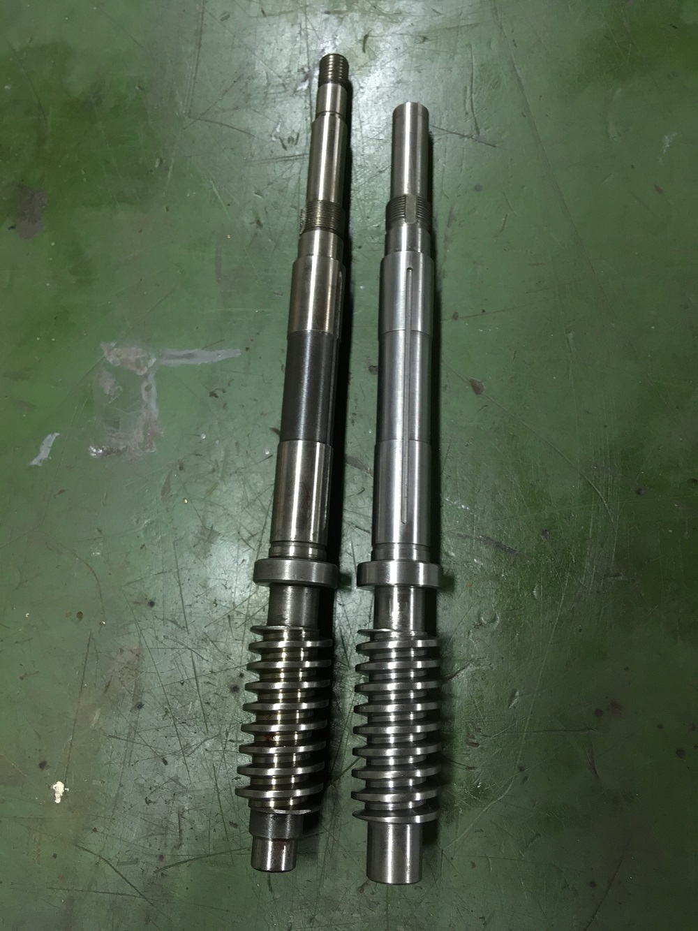
Both shafts
Assembled new shaft assembly
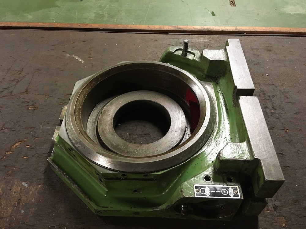
Rotary table casting
Thank you for viewing
The Home Engineer


 Reply With Quote

Bookmarks