
 LinkBack URL
 About LinkBacks


Modestly equipped factory ~ Satisfactory equipment?.........Yes, with good planning and minimal expense.
Bulk of my recent posts concern a working environment. Whether profit's involved or not, little improvements make a difference. When a machine occupies space, think how it can swing from second operation to primary and back.
This one's about a drill press.
While an import, I really can't identify any faults. The few shortcuts were easily remedied.
a] Moved it to where it's standing next to the turret mill. Now I drill, countersink or deburr, counterbore, tap, ream etc 3 steps away instead of 40. All those operations appreciate coolant; drill press is equipped for flood, where mill [as yet] only mist.
True flood coolant needs; decent drainage [inc. unrestricted hoses], swarf baffles, a sump, return pump & switch, readily aimable nozzle, shut-off valve, and coolant. Without kerosene or Stoddard solvents to clean parts, you'll want to run water based solutions, as we do. Every day, I run aluminum, stainless and carbon steel in fairly even quantities, so dilution ratio is based on stainless.
b] The drill press had the mechanical features, a few needed tuning.
1] Trough drain opening was vertical and wide open. Machined a simple un-threaded hollow plug with side holes. It's sealed with a bead of plumbing putty.
Sizing of holes and plug ID restrict already marginal flow. A tiny ball valve controls volume fed. Takes 1/2 an hour at full volume to reach point of over running the trough. Calculated [I thought] enough surface area of holes to drain equivalent to feed rate.
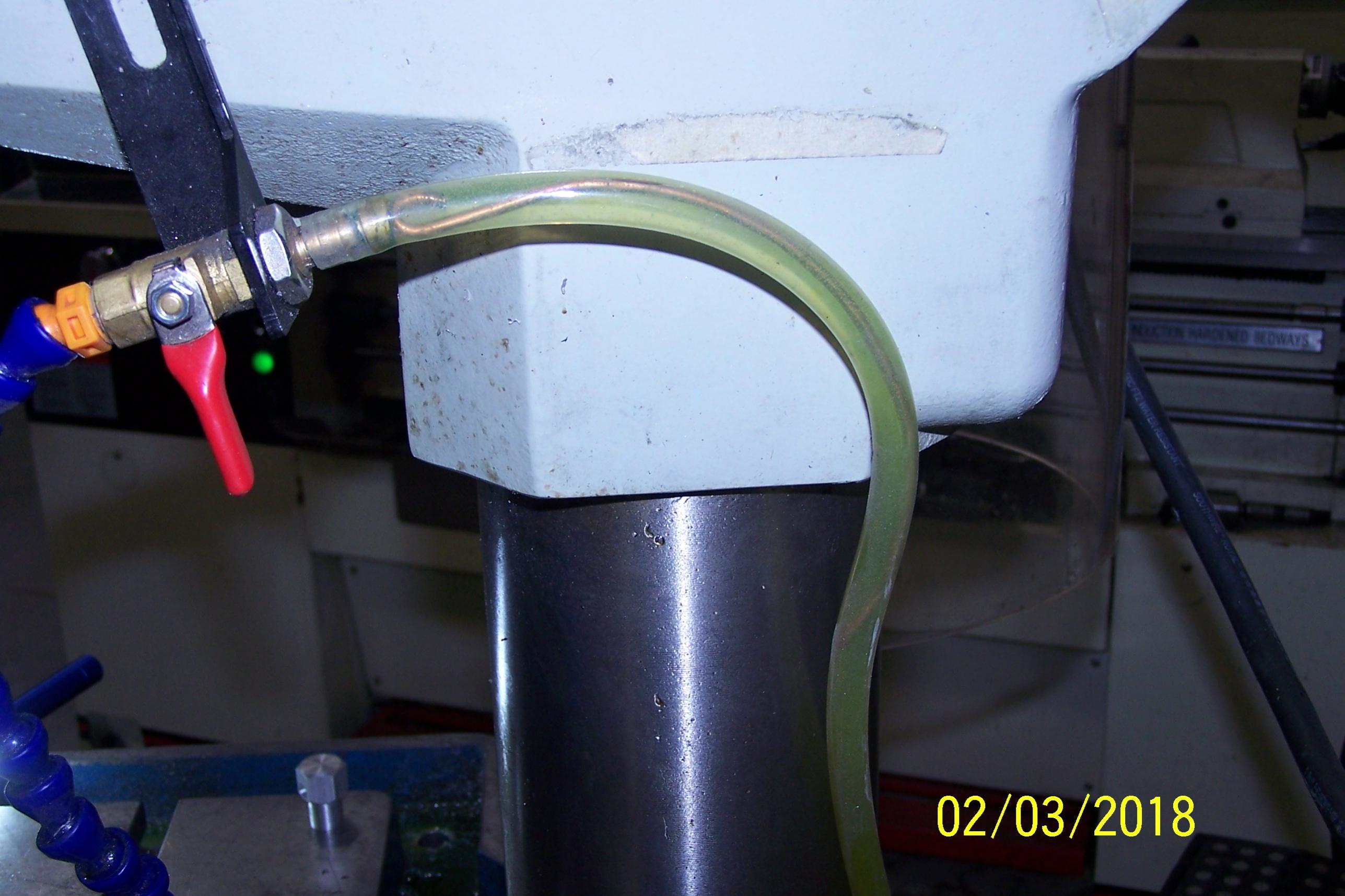
2] Both pressure and drain hoses curl uncontrollably. Alleviated with welding wire, formed to suit desired shape inside the clear vinyl hose.
A flattened loop in one end, barely larger than ID, secures it fine. Most important one is hose of table drain into sump of machine base! Unless you prefer mopping up...
3] Made a shield for motor fan.
In this part of the world, chips tend to gravitate earthward. Motor casing seems to be inviting target for chips, but now to bind up motor, they'll need some gymnastic prowess.
4] Calculated sump volume, that quantity is marked on the motor fan shield.
At the very first use, pleased to have everything functioning as planned. Can enjoy power feed, auto-depth stop, tapping functions easily, improved finishes of course, and shares production burden with mill more effectively.


 Reply With Quote

Bookmarks