Free 186 More Best Homemade Tools eBook:  
New: 300+ fresh build posts/day from 275 forums → BuildThreads.com

User Tag List

Results 1 to 2 of 2

Thread: Ruggedised temperature sensors

Threaded View

  1. #1
    Supporting Member tonyfoale's Avatar
    Join Date
    Nov 2016
    Location
    Spain
    Posts
    1,821
    Thanks
    834
    Thanked 3,238 Times in 910 Posts

    tonyfoale's Tools

    Ruggedised temperature sensors

    Recently I made a post outlining a shock dynamometer that I'd made. http://www.homemadetools.net/forum/s...amometer-56478
    In that post I mentioned in passing, the temperature sensors that I used on the shocks being tested. There seems to be some interest in these sensors in their own right, hence this post which will go into greater detail. I have made several of these sensors and use them in various applications such as the shock dyno mentioned but also on a flow bench as another example. The flow bench will be the subject of another post in the future.

    Click image for larger version. 

Name:	Board_10.jpg 
Views:	315 
Size:	116.4 KB 
ID:	16183 Click image for larger version. 

Name:	Board_11.jpg 
Views:	315 
Size:	81.4 KB 
ID:	16184
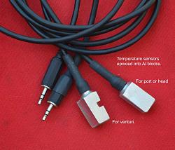
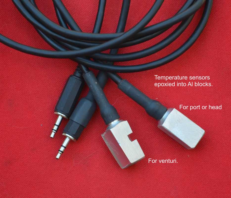
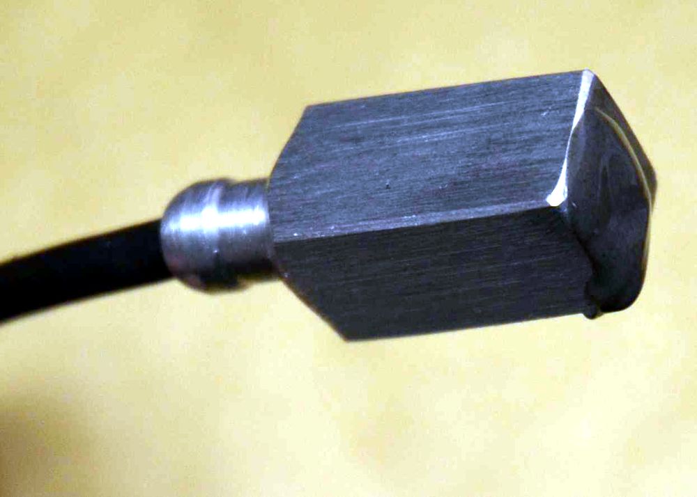
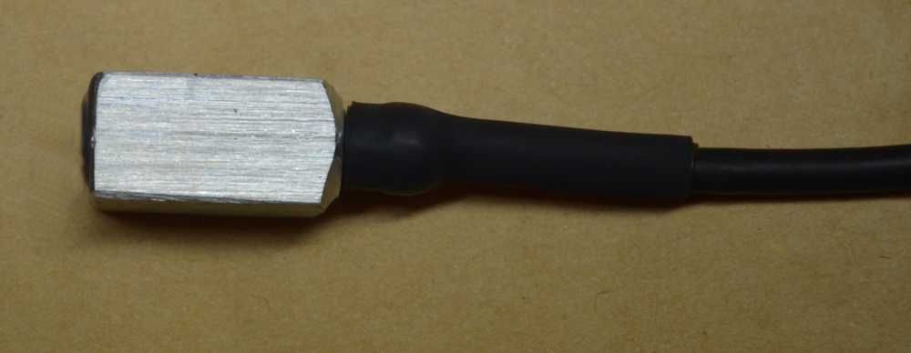
    Here are examples of the finished sensors.

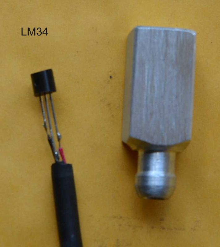
    The base sensors are of the semi-conductor variety and in many applications they are too delicate without some form of protection. To that end I make an aluminium housing to suit the application and pot the sensor using epoxy. I use either an LM34 (deg.F) or an LM35 (deg. C) chip which are simple 3 wire analog devices. There is an earth or common wire, a power supply wire and the 3rd is the DC signal output.

    Click image for larger version. 

Name:	Temperature_01.jpg 
Views:	315 
Size:	41.4 KB 
ID:	16185 Click image for larger version. 

Name:	Temperature_02.jpg 
Views:	316 
Size:	22.7 KB 
ID:	16186
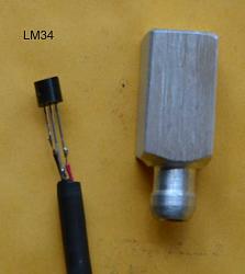
    The sensor shown with my housing prior to potting in epoxy.

    Click image for larger version. 

Name:	temperature_04.jpg 
Views:	328 
Size:	38.7 KB 
ID:	16187 Click image for larger version. 

Name:	temperature_05.jpg 
Views:	307 
Size:	61.5 KB 
ID:	16188
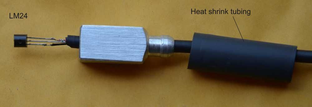
    On the left the sensor and soldered cable encased in wet epoxy, next we see the sensor potted in the housing.

    Click image for larger version. 

Name:	Temperture_06.jpg 
Views:	325 
Size:	26.2 KB 
ID:	16189
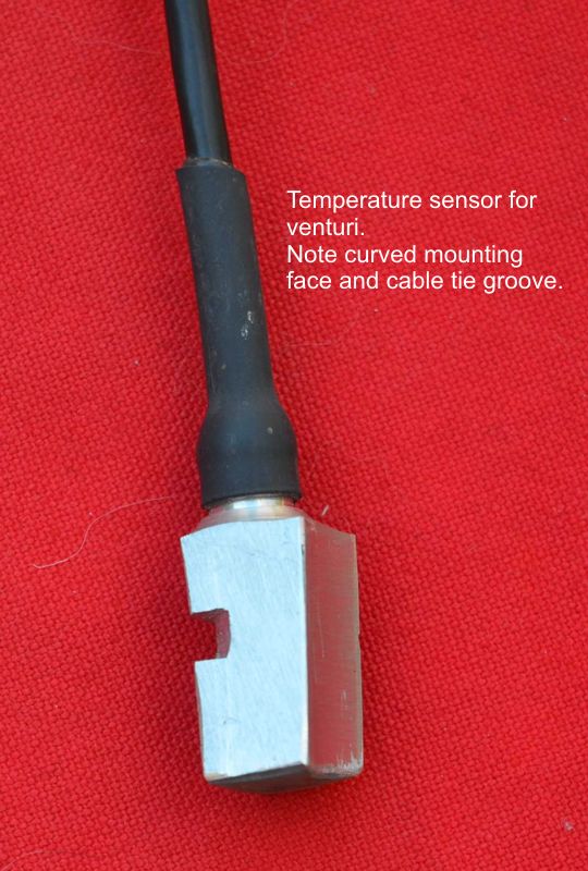
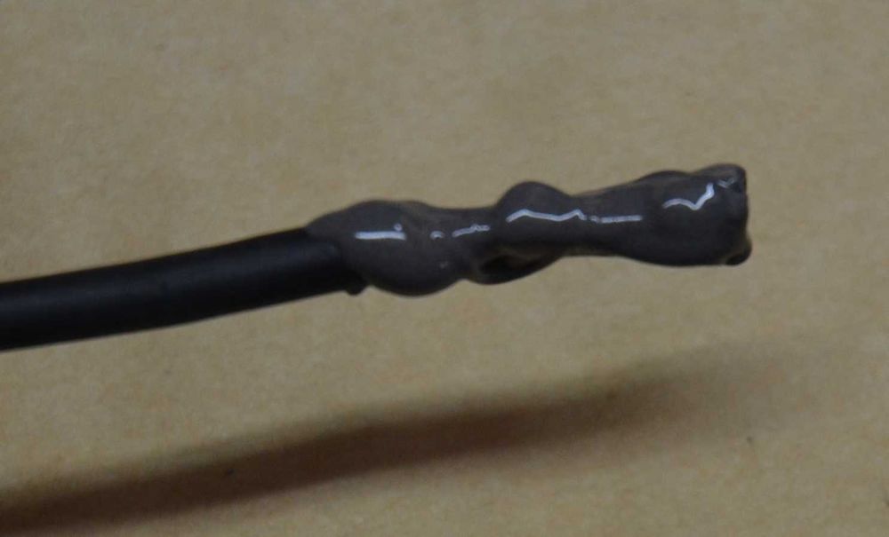
    Some heat shrink tubing over the cable entrance is used to seal it and provide support for the cable. This finishes the assembly and makes it suitable for harsh environments.

    Click image for larger version. 

Name:	TempSensor01.jpg 
Views:	335 
Size:	38.9 KB 
ID:	16190
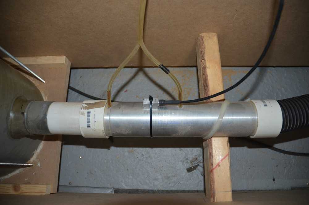
    Here is an example showing a sensor fitted to a venturi used for flow measurement.

    I'll go into more detail of how I deal with the output signals when I make the post on the flow bench.
    Last edited by tonyfoale; Jan 20, 2017 at 09:05 AM. Reason: Added link to shock dyno post.

  2. The Following 3 Users Say Thank You to tonyfoale For This Useful Post:

    DIYer (Jan 21, 2017), Jon (Jul 18, 2019), PJs (Jan 21, 2017)

Thread Information

Users Browsing this Thread

There are currently 1 users browsing this thread. (0 members and 1 guests)

Tags for this Thread

Bookmarks

Posting Permissions

  • You may not post new threads
  • You may not post replies
  • You may not post attachments
  • You may not edit your posts
  •