19 Attachment(s)
Fabricated shaft and box housing
The clutch linkage is nearly complete and I thought I would share how I fabricated the shaft and made the the box housing with different soldering techniques I use.
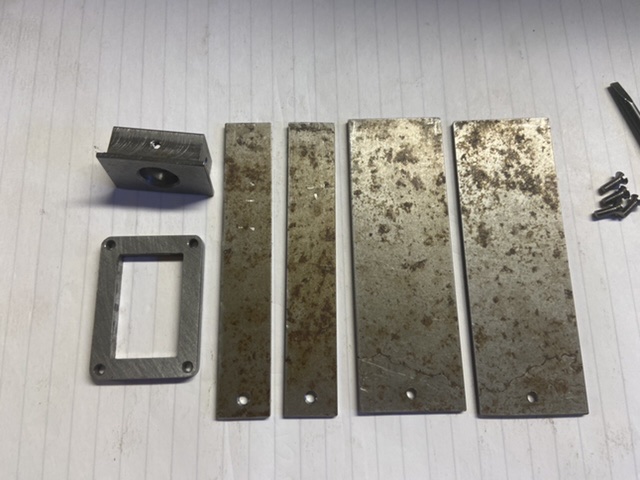
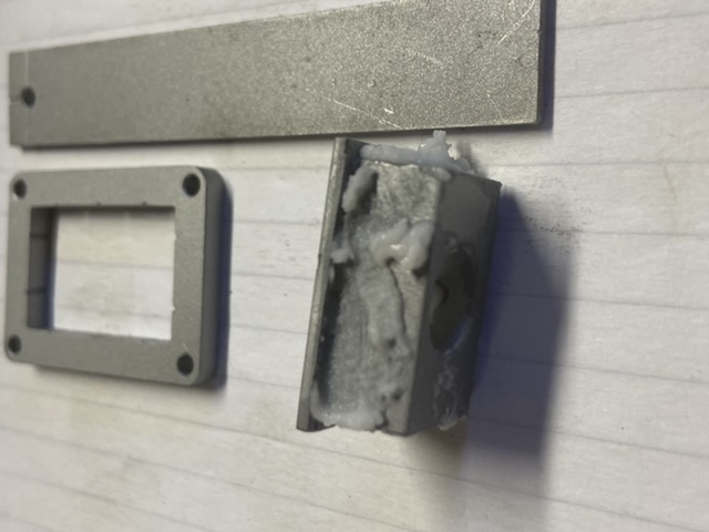
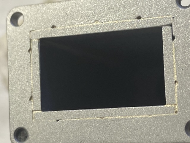
The box is relatively straight forward as it is screwed together and a mounting flange at the bottom. However screwing matting faces together is not great for silver soldering as there is no gap for the solder to capillary into. To over come this I file notches and grooves where I want the solder to flow. This doesnt give satisfactory joints for pressure fittings but is great for fabricated components. The notches and grooves allow the solder to penetrate the joint as can be seen in the photos below.
Attachment 35014 Components to be silver solder together.
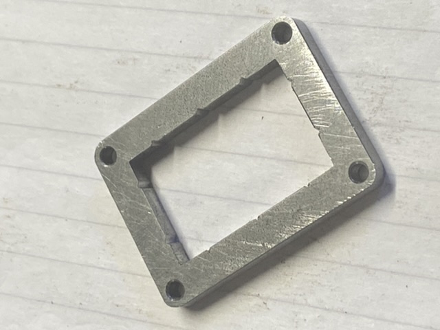
Attachment 35015 Filed notches can be seen on the inner part of the flange.
Attachment 35016 Flat plates that are to be screwed to top bearing block.
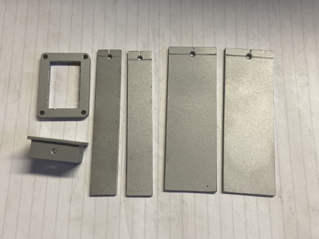
Attachment 35017 All shot blasted ready for assembly and fluxing.
Attachment 35018 Top bearing housing fluxed ready to accept plates.
Attachment 35019 The seems are also fluxed on the inside.
Attachment 35020 Base flange is a tight push fit over plates.
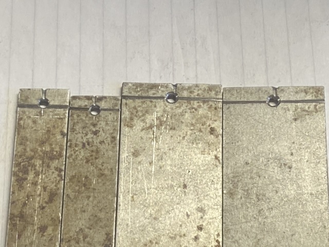
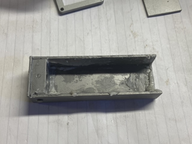
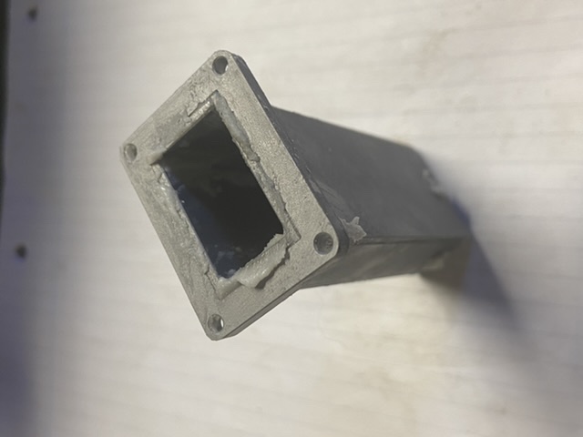
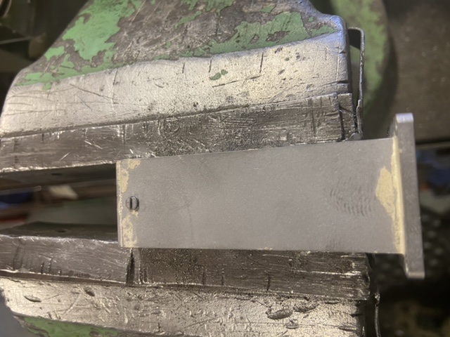
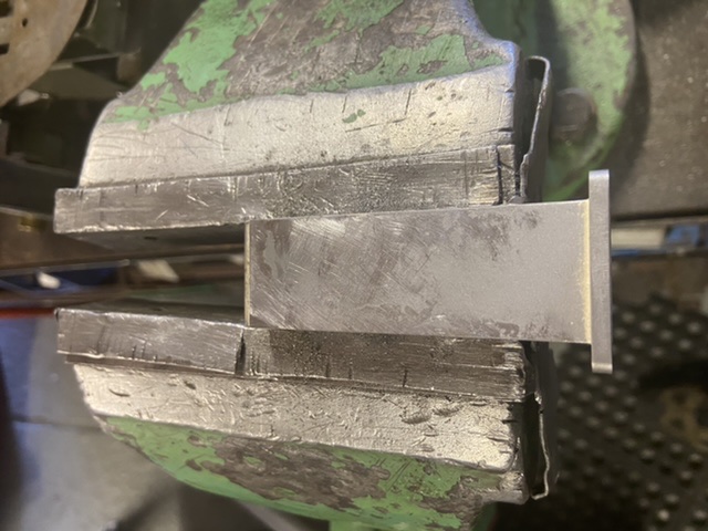
Attachment 35021 Attachment 35022 The photo shows that the solder has penetrated the base flange joint.
Attachment 35024 Attachment 35025 The heads of the screws are filed off.
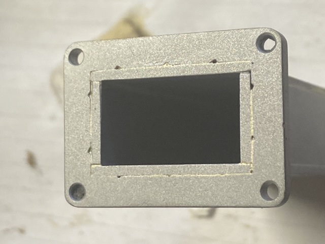
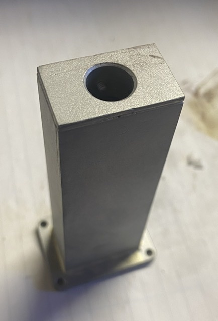
Attachment 35026Completed box housing for clutch linkage.
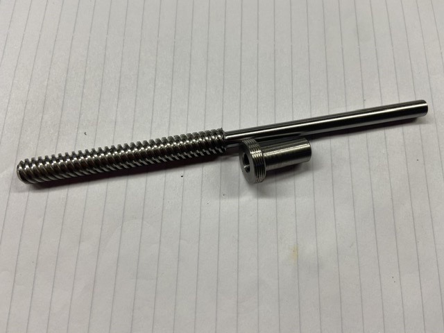
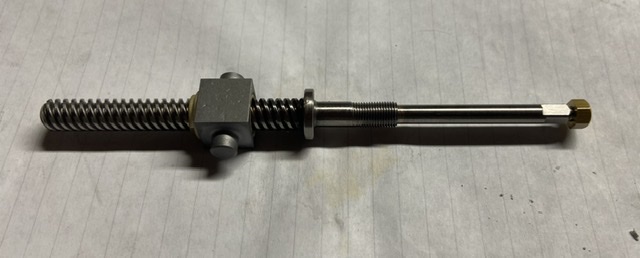
The shaft is made from a commercially available stainless steel 8mm diameter 4 start thread and a brass flanged nut to suit.
As this requires a flanged section this is rough turned over size and silver soldered in place. The shaft and the flange section can then be placed in a collet and turned true to each other and to size. The shaft is 3/16diameter and the flanged section drilled 0.004 (0.1mm) bigger to create the gap for the capillary action.
Attachment 35027 Shaft and flange
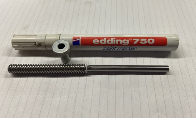
Attachment 35028 Again to stop the solder flowing were it is not needed the paint pen is used.
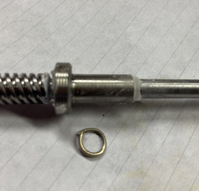
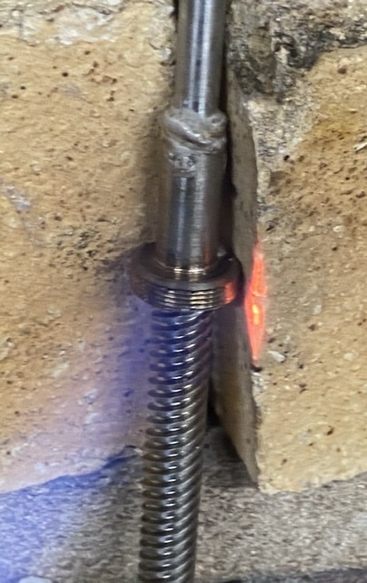
Attachment 35029Attachment 35030 A silver soldering ring is bent up and placed on the joint and fluxed.
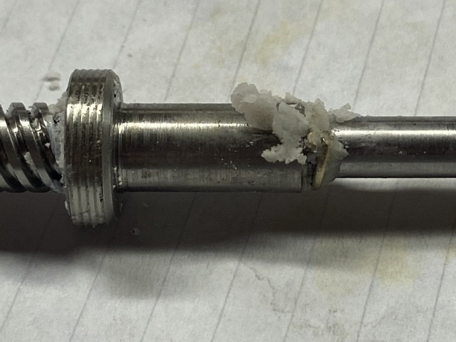
Attachment 35031 Heat is applied to the largest section and the heat draws the solder into the joint.
Attachment 35032 Completed shaft awaiting top bearing and locknuts.
Thank you again for viewing and hope this will help those starting out silver soldering.
The Home Engineer
7 Attachment(s)
Fabricated dog bone linkage
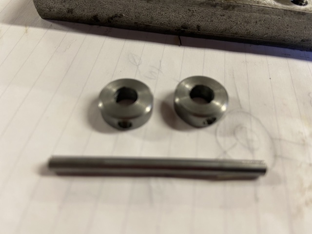
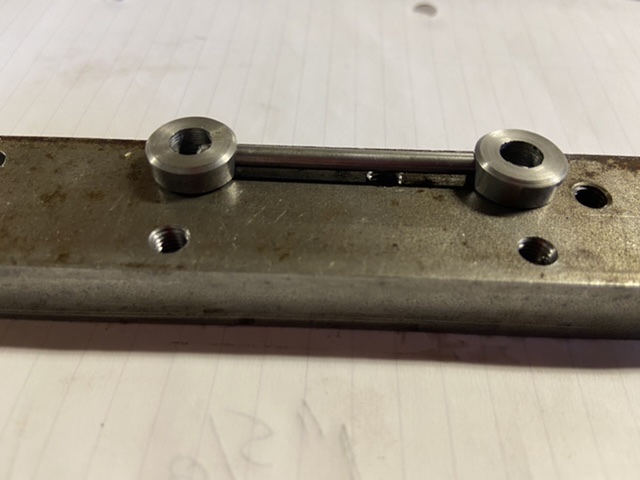
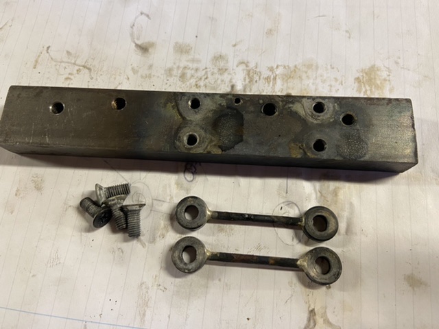
Nearly on the final stretch of the clutch linkage. The last of the fabricated parts are the two dog bone links which again are a silver soldered fabrication. The most important thing is that the links have both the same hole centres (pitch). To achieve this a scrap piece of material is drilled and tapped at the correct pitch and the ends of the dog bone linkage are held in position with countersunk screws and the tie bar fitted into drilled through holes. The fabrication is completed by soldering the joints.
Attachment 35041 One dog bone link machined ready for soldering.
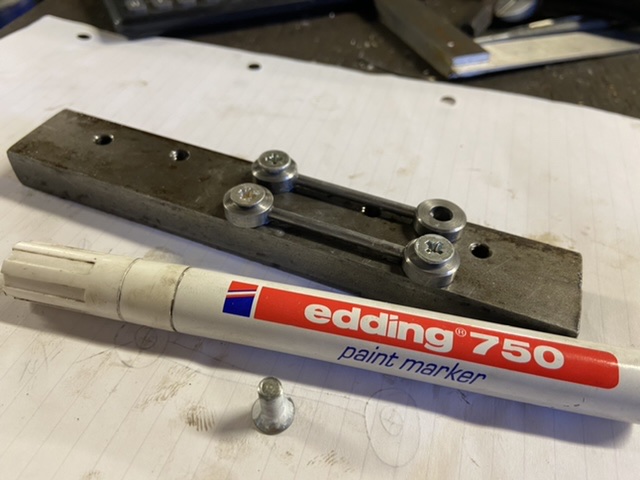
Attachment 35042 Soldering jig
Attachment 35043 Screws painted to prevent solder contact.
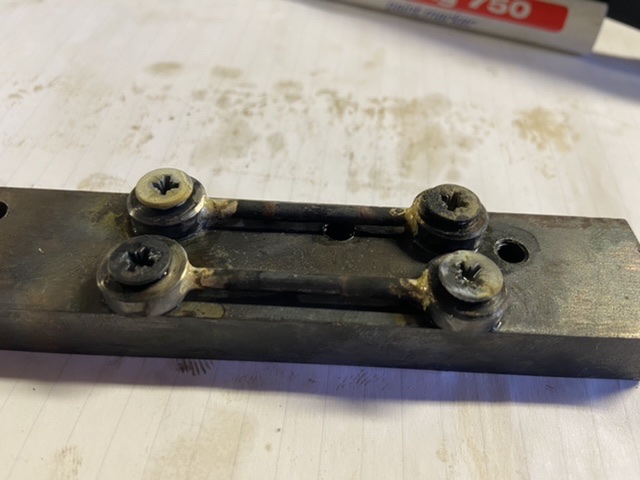
Attachment 35044 Soldering completed.
Attachment 35045 Removed from jig.
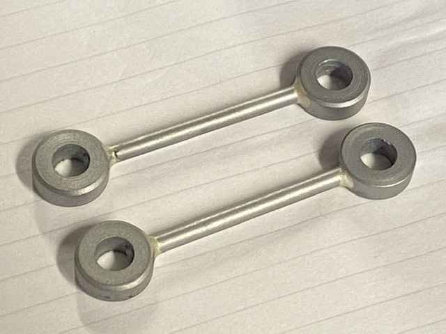
Attachment 35046 Cleaned up using shot blasting and the holes need to be reamed.
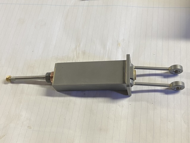
Attachment 35047 Completed assembly awaiting operating handle. (Not sure if you make single crank or wheel type).
Thank you for viewing
The Home Engineer
