
 LinkBack URL
 About LinkBacks


I'm running a lot of angle iron for next machine frame. Most pieces are longer than mill table, up to 13'. A vise, even our matched pair, aren't much help. Using DRO to extremes of travel makes their weight bear heavily on the ways, plus angle not that great a profile to clamp. I find clamping direct easiest, angle leg 'down'.
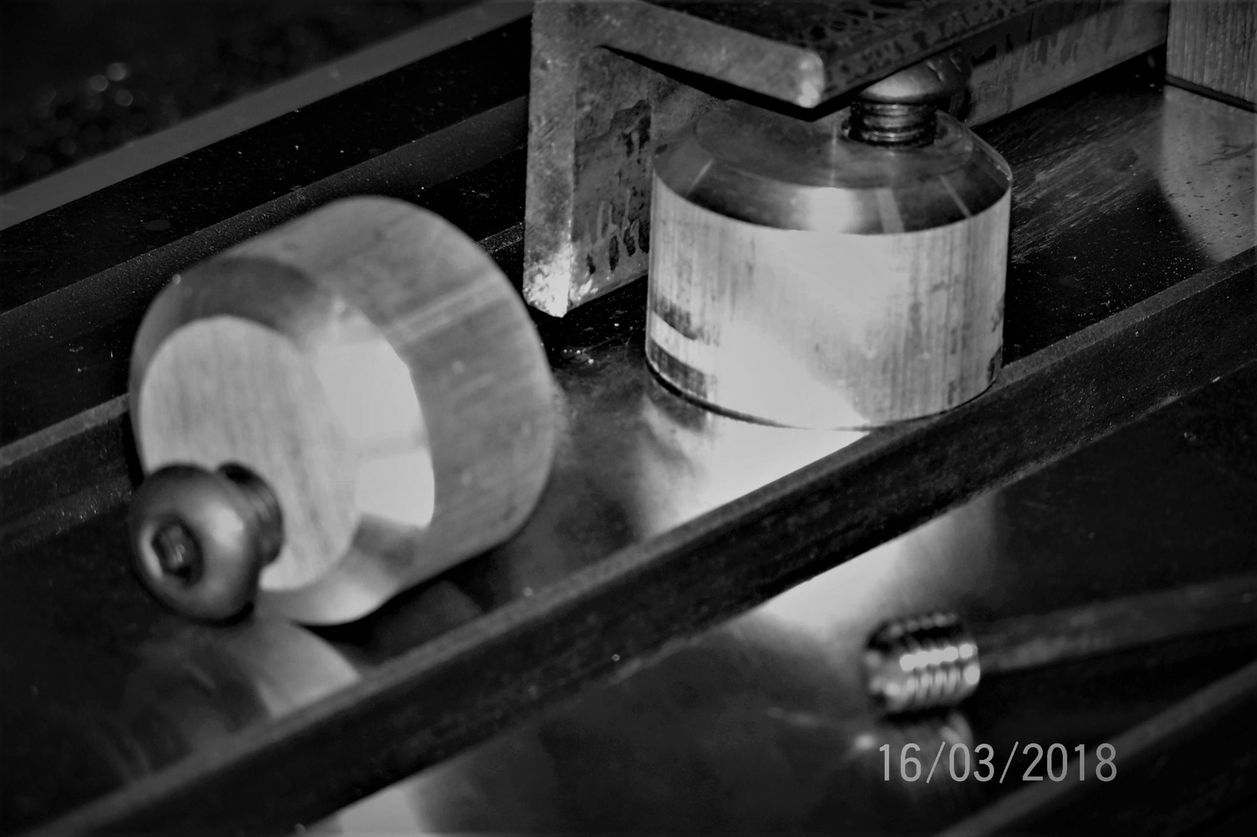
These jacks are tapped well away off center, 3/8"-16 through, and middle of foot is relieved.The deep chamfer clears corner of inside radius [fillet] of angle iron. Button heads go deeper into corner than flat heads. Height set so leg is not in contact with table. A set screw runs in from bottom, locking the screw. Lowering profile is possible with screw counterbored, but I would use steel, for better strength in remaining threads. Longer screws make these widely adaptable. Made 4, 3 is sufficient. In clamping, 3 is a good number; allowing 1 to be moved while 2 hold the parts location. So why 4? So one can be set offline and exchanged, or used as a gauge in setting the others.
My process;
1] Lay out X coordinates as references. I mark prints with colored pens to ID location and size combinations. Premarking X coordinates keeps clamping from obstructing drills, countersinks and taps.
2] As many locations are drilled allowed by table travel.
3] Table returned to starting position and material set to new address. Pin gauges register existing hole at new address. Input last location to DRO. This maintains drawing accuracy nearly absolute instead of incremental positioning.
4] Y axis is preserved by tight fitting keys standing in tee-slots, in direct contact with material.
Compact bar clamps secure angle rail to keys in set-up, secured using short jacks under strap clamps.


 Reply With Quote

Bookmarks