
 LinkBack URL
 About LinkBacks


I needed to make some specialized angle blocks for another project specifically, I needed to take a 4 inch bar and make one side 7.5 degrees to the opposite side. Since the piece was so long, I needed to support it at both ends, so using my standard issue angle blocks was not going to work.
Joe ∏ addressed this 3 or 4 years ago, and I would like to present it again.
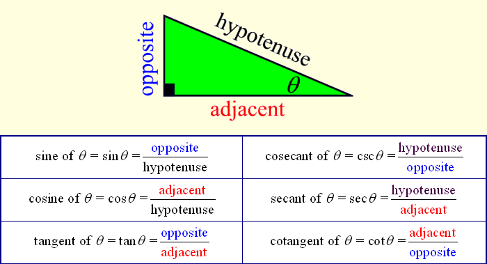
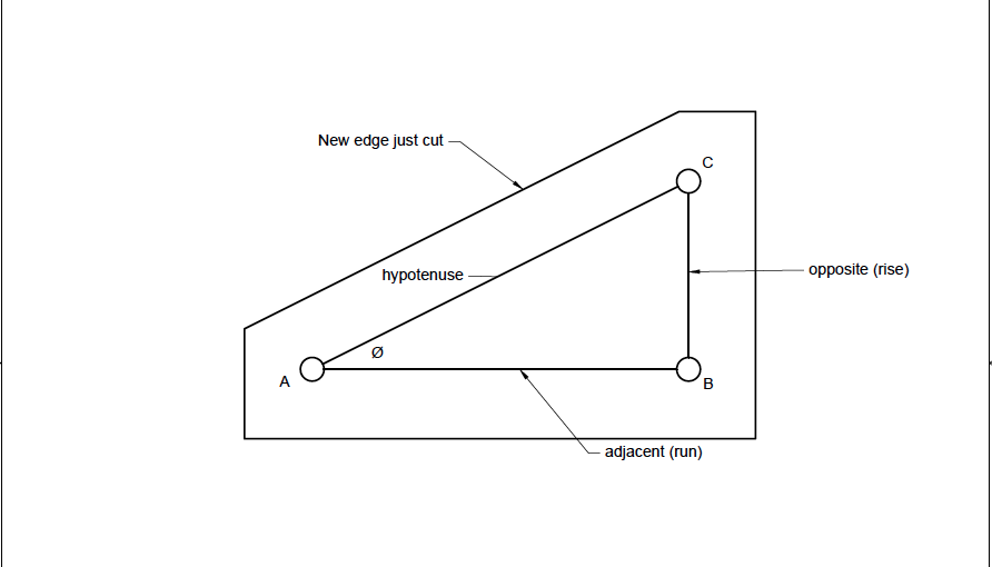
First of all, this graphic summarizes most of what we need to know about trigonometry:
(I printed this picture and I keep it handy for reference.)
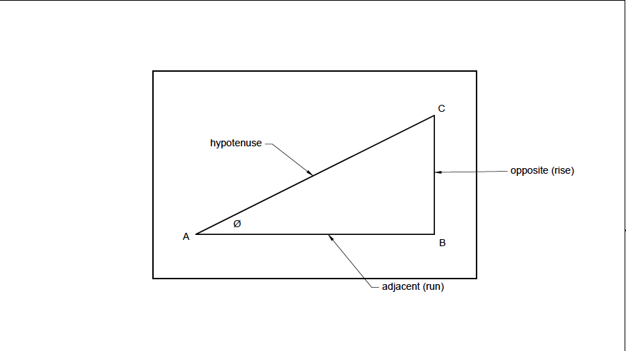
For my project, I started with two identical squared pieces of aluminum, and I needed to find points A, B and C so that the angle Ø was 7.5 degrees. By squaring the blanks first, I was confidant I could use any of the edges to indicate my angle plate later.
The length A to B doesnt matter much, so I chose 1.5 inches. (As you will see later, it is important that the distance between A and C is less than the width of your vise jaws.)
Using the definition tan Ø = opposite/adjacent, and multiplying both sides by adjacent, you get the formula tanØ x adjacent = opposite.
Plugging this in my calculator: 7.5 [tan key] x 1.5 = 0.1975
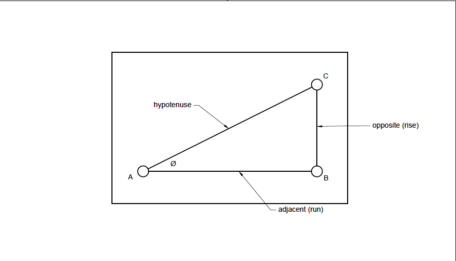
So I drilled and reamed the hole at A, ran the x-axis 1.5, then ran the y-axis 0.1975 and drilled and reamed hole C.
For this case, there is no need to put a hole at B. In other instances it might be beneficial so you could put pins in either A & B or in B & C to register your soon to be cut angle off the edge a part or off the slots in your table.
I then put pins in both holes. In my case, I was making 2 identical parts so I put the pins through both blanks.
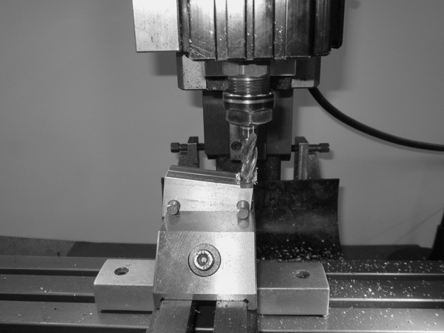
The pieces are then placed in the vise with the pins firmly against the top of the jaws. (You could add parallels on top of vice if the pins are too far apart to fit on your vise, but that decreases the amount of material you have to hold them.)
Then I simply cut the pieces to give me a precise 7.5 degree angle block.
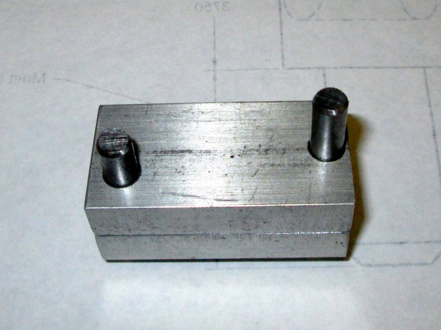
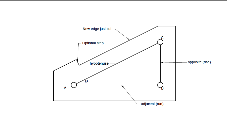
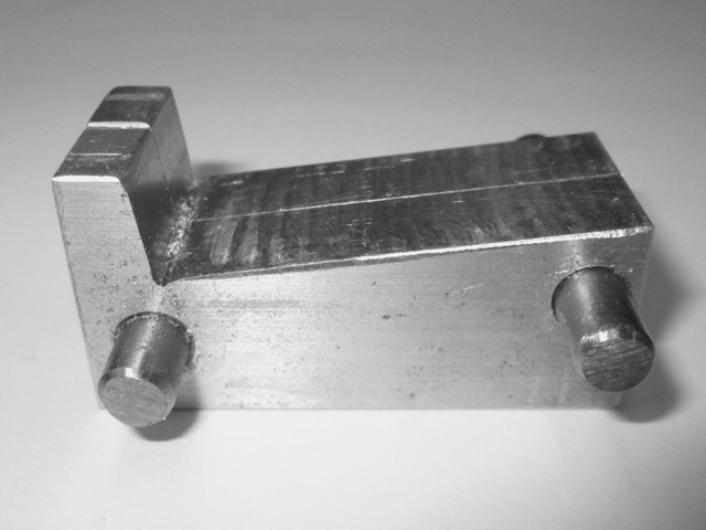
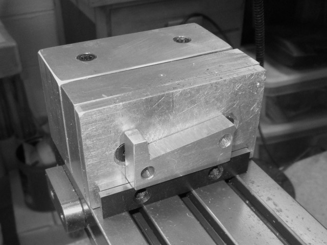
I wanted to be able to register both blocks on my table, so I added an optional step in them.
And here is one of the blocks in place.
I hope this was interesting and that it helps you tackle another project.


 Reply With Quote

Bookmarks