Inexpensive and effective approach for sharpening and split-pointing drillbits
https://www.youtube.com/watch?v=IcbEK1P1Oys
Printable View
Inexpensive and effective approach for sharpening and split-pointing drillbits
https://www.youtube.com/watch?v=IcbEK1P1Oys
Hello Bob,
This is what we call now a diamond point, on this video I'm not in accordance with the use of the wheel freehand, it's dangerous if it broke and that can comes easily.
When I was an apprentice we learn to cut the rear angle on the same grinding tool we use normally and with the protections included, now it's no more authorized to learn that to apprentices because people have the bad attitude to take protections out, but when made correctly it's without danger.
First of all, thanks for watching and for your honest feedback.
I'm not sure that I agree with that. Eye protection is a must, of course. But this cutoff wheel only weighs maybe 20 or 30 grams. So if it breaks, while it could definitely mess up an eye, it's pretty much harmless to the rest of my body, at least as far as permanent damage goes. I don't count a little scratch on my hands or arms as "danger".Quote:
Originally Posted by Okapi
I also have pneumatic and electric cutoff tools. A full size cutoff wheel is much larger and has a lot more mass. Those I could consider dangerous to use in this fashion. (Even though I still do it, I admit that I'm doing something dangerous. :rolleyes: ) But these little tiny dremel cutoff wheels just aren't dangerous, outside of eye protection.
Make the speed calculation, at 20'000rpm, what is the energy in Joules of 30 grams, it's a nice small bullet, I'm not in accordance to say it's not dangerous, and if you simply touch a finger at this speed can make some damages too(I had a problem with my 90'000rpm dentistry tool with a diamond head less than 1 gram which broke and need chirugical action to take it out of my arm…).
<!-- BEGIN /var/www/html/homemadetools/protected/modules/zeus/views/tool/postUpdate.php -->
Thanks bobneumann! We've added your Split Point Drill Bit Sharpening Method to our Sharpening category,
as well as to your builder page: bobneumann's Homemade Tools. Your receipt:
<div id="blocks"> <div class="block b1 pngfix"> <div class="bimg"> <div> <a href="http://www.homemadetools.net/homemade-split-point-drill-bit-sharpening-method"> <img src="/uploads/220109/homemade-split-point-drill-bit-sharpening-method.jpeg"/> </a> </div> </div> <div class="head pngfix"></div> <div class="left pngfix"></div> <div class="right pngfix"></div> <div class="blockover b1 pngfix"> <div class="title"> <a href="http://www.homemadetools.net/homemade-split-point-drill-bit-sharpening-method">Split Point Drill Bit Sharpening Method</a> <span> by <a href="http://www.homemadetools.net/builder/bobneumann">bobneumann</a></span> </div> <div class="tags">tags: <a href='http://www.homemadetools.net/tag/drill-bit'>drill bit</a>, <a href='http://www.homemadetools.net/tag/sharpening'>sharpening</a> </div> </div> </div> </div>
<!-- END /var/www/html/homemadetools/protected/modules/zeus/views/tool/postUpdate.php -->
Not siding with any parties; but it is accurate to see both are correct. All tools carry that instant of failure, whether it occurs or not. I'm no safety-fascist, few events are are manageable afterward. But others can be minimized with certain protective measures.
I'd think mini tool wheels good point splitters; but with a simple V-block for the bit and yoke for motor. Split points have to be centered to penetrate where intended.
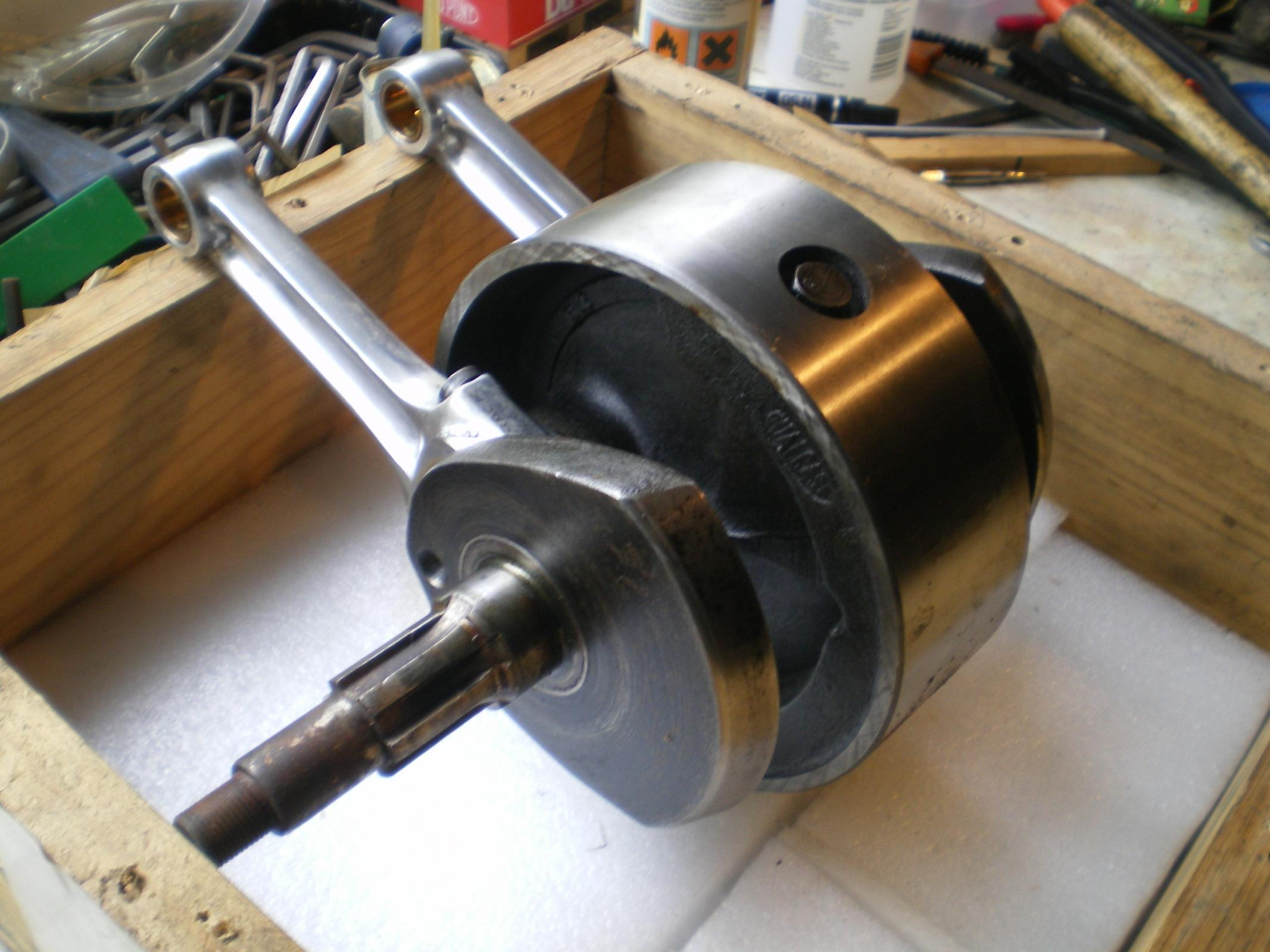
There have been times when I have had to sharpen drill bits in the field using whatever grinding device I had at hand. My welding rig had a "V' trap on the back of the bed for welding small pipes or other things I usually would clamp the grinder in the "V" leaving both ads free for working the bit.
I won't condemn nor condone double free hand I'm not the one who had to or chose to do it that way. I'll just say that I would not mostly due to the lack of absolute control over the grind angle I have split point / diamond point whatever you want to call it bits on a belt sander I actually prefer to sharpen my bits larger than 3/4" on my belt sander
Living is dangerous, it always ends badly, whereas sharpening a drill bit freehand only ends badly in a small percentage of cases.
Should we stop living or stop sharpening? I'll play the percentages.
Well that says it all really, is that an original observation as I have not heard it before but its a keeper.Quote:
Originally Posted by tonyfoale
Alan,Quote:
Originally Posted by olderdan
It was an original observation but I am sure that the same sentiments have been expressed by many others.
OHHHH,,,OHHHHHHHHHHHHH OHHHHH OHHHHH OHHHHHHHHHHH!!!!!!!!!! (channeling sam kinison ) oh how could u us the SIDE of grinding wheel!!!!!!!!!!! how do i get OSHA to come and pay u a visit !!!!!! and then your state version of OSHA !!!!!!! i have NEVER in my 41 years of machining experience seen anyone use the side of a grinding wheel for anything...way too dangerous, a wheel breakage at 3200 rpm or even 1750 can really tear u up !!!!! ok rant done,, i have always used the proper face of grinding wheel to sharpen drill bits,and grind a thinning of the web if needed when drilling by hand,,too..i will however try your way sometime, but all of the drill bits i have bought or used have always had the regular point and work just fine,,i would like to know how long your split point does hold up ,do a test,, drill more of that plate steel till dull,without cutting oil, and let us know,,
Grinding on the side of a wheel, agreed, can be risky. But the amount of pressure to point a drill this size isn't likely to fracture a sound wheel. It's more when grinding puts a groove in that surface initiating a weakened secondary periphery, and reacts to centrifugal force. Remember, side-wheeling isn't all that rare on reciprocating [surface] grinders, it's just better controlled alignment.
Quote:
Originally Posted by madokie
Ok. OK. OOOOKKAAAAAAYYYYY! You've converted me.
I hereby swear that I will never again admit to grinding on the side of my wheel on a regular basis. It didn't happen. Nothing to see here. These are not the Droids you're seeking. Return to your happy place, knowing you've saved me. 😉
yes i agree SOMEPEOPLE may use the side to grind on, but the real problem is some wheels (cheap asian)have a small runout on the side and u cant dress the side either...and bench grinding wheels are not made to grind on the side either..as are surface grinding wheels,,i have never seen a bench grinding wheel explode but i dont want to either, and if your working alone in your shop,,and something REALLY bad happens u might not survive it...working alone u MUST be more careful and not be in a hurry,,say bob u look to have a bunch of bench grinders, where are all those wheels from?????? CHINA ???? !!!!!!! another good reason NOT to grind on the side !!!!!!!!!!!!!
You warn against grinding on the side but without giving any real explanation of why. You mention side runout but I have fixed that with either or both careful mounting and/or truing with a diamond. I have been sharpening tools on the sides for around 60 years and this is the first time that someone has told be not to.Quote:
Originally Posted by madokie
You can buy bench grinders with rests designed for grinding on the side, are all the manufacturers and users of those as uninformed as I obviously am?
I'm not totally in accordance with Tony's explanation, they are grinding wheels made as cups(or others for 45° use) for grinding on the lateral part, all makers of grinding wheels explain that you never use a wheel made for perpendicular use as a lateral use, you find it that on makers like Norton, I've only the french catalogue from Norton but you can found the same in english on the web easily.
They explain to never use on the side a wheel cup or another when the thickness is less than 10% of the diameter, then 30mm. for a 300mm. wheel etc…
Attachment 27545
Just as Tony and others describe, side-wheeling on bench grinders is not unheard of, and safely pursued by a sizeable group of workers. That manufacturers advise against it, has at least two faces. One is a wheels design intent, coupled with how its made. The other avoids litigious involvement with a careless public, and government agencies.
I didn't give any explanation, I asked a question which has not been answered yet.Quote:
Originally Posted by Okapi
WHY should I break the habit of a lifetime and stop tool sharpening on the side of flat wheels?
As advised I looked on Norton's site but the only relevant text that I could find was a list of DOs and DON'Ts. The DON'Ts said avoid the side but without explanation.
I have never been very good accepting DOs and DON'Ts as plain statements, but I will always consider an explanation. When someone tells me not to do something I expect that they will know WHY and be able to explain it to me. So far in this case the WHY is lacking.
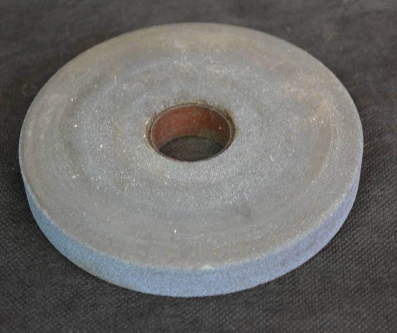
Grinding with the side of the wheel is accepted practice in machine shops on both surface and cyl machines. The wheels are usually backed of by hand to leave a ragged edge to prevent burning of the material. The flywheel assy shown is an example where the edges have a cross hatched finish, this was done with a 12 x 1 inch wheel. Attachment 27556
These wheels are available already dished for this purpose.
For bench grinders the only way to get a flat face instead of a concave one is to use the side of a diamond trued wheel with common sense pressure, same goes for any freehand use. Any protection is a personal choice unless instructing beginners, probably best to agree to disagree on this subject.
We are cutting hairs in four to translate from french, excuse-me tony if i use explanation in place of writing or similar.
I'm always working with the idea to transmit goods infos to the apprentice and to use safely the tools etc…, the question on "why" can be easily found on every book for mechanical apprentice when it was authorised to use some tools before CNC, as I've not read the more recent edition, I suppose they explain simply that if you have your piece entrained by the wheel in the protection carter it's about 90% more chances to see the wheel broken that on the good side.
If it's not necessary to use specific wheels, why making so many cup wheels(and a lot of others forms) witch are a lot more comfortable and with a lot more efficiency than plain ones ?
After that, if you want to make the same manner you use the tool since decades, it's your business, but they can be others ways to arrive at the result needed more safely.
When ever I replace the wheels on any of my bench and arbor grinders which is rare, the first thing I do is true all 3 sides of the wheel.
This aids in getting them balanced also reduces the likely hood that the wheel will have problems later in use life.Helps the grinder to run smoother and quieter.
in my 55 years of being around bench arbor and hand held grinders I can count on 1 hand the incidents I have seen a wheel fail none have ever been from grinding on the sides. I don't make a habit of using the sides of a wheel as the primary cutting surface but when or if the circumstances dictate I will use them.
Where I have seen people have problems in in not keeping their wheels cleanly dressed and grind until they have deep grooves in their wheels usually I see the groves directly associated with the angled "V" grove in the tool rest that so many use as a guide to sharpen their drill bits. I don't like having those made in groves and do not use them most of my bench grinders do not have one. I prefer to free hand and move the drill bit or tooling cutter across the entire face of the grinding wheel. My thickest grinding wheel is 1 " and even at that it does not have a wide enough surface area to sharpen some of my drill bits So I will get the profile as near as possible then finish up on the side or finish up on a belt sander.
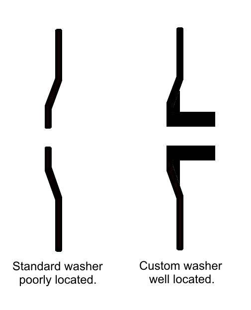
In my experience even cheap grinding wheels are made very flat and of even thickness. If that is generally the case then any lateral runout must be due to the grinder itself. Bench grinders generally have wheel washers which are quite thin and which bear up against inadequately sized shoulders on the shaft. This locates the washers very poorly as regards to wobble.Quote:
Originally Posted by Frank S
This is easily attended to and only needs doing once for any particular grinder.
I junk the inner washers and make a combined washer and stub shaft to hold a wheel with a larger diameter hole. I make this washer/shaft piece to be a light push fit on the grinder shaft. Unless the grinder shaft is bent this ensures that the washer will hold the wheel with the minimum of lateral wobble. Only rarely have I needed to true the sides of a new wheel.
Attachment 27585 Click for full size images.
Wheel with oversized hole.
Attachment 27587
This shows the comparison to the usual stock wheel inner washer of the custom washer/shaft that I use.
I use the narrow style washer on the outside of the wheel because that is free to align with the wheel, all the location is done by the inner custom piece.
Tony, I am in full agreement with your observations, on my bench grinder the locating shoulder for the inner washer is only 2mm larger than the thread, couple that with a cheap stamped washer its not surprising that run-out is common. The only only wheel that has run true from the off is my CBN cup wheel and that is the one I had to make a custom mounting for. The next time I need a wheel change I will copy your idea.
Thanks for finally explaining it well. Dad was a mechanical engineer (10+ us patents) and he could never explain it to me in simple lay terms as you have. My evidence is a box full of inconsistent bits. Now if I can find the time for resesutating 100 bits.
Thanks for your feedback. That's my whole purpose in making videos is sharing back some of the things I've learned along the way. Your post has made my day!
Yup, life is 100% fatal.
Alright, I've a hack this thread reminds me of. Are there extra points if a thread hack and a work trick coincide?
Tony's 'bushed washer' for bench or pedestal grinders seems related, to an odd surface grinder application.
Lots of surface grinders carry 1.25 [31.75mm] ID wheels. Generally the wheel shroud/ guarding indicate largest wheel diameter, zillions are 6", 7" and 8". Average surface grinders, 5" x 10", 6" x 12", 6" x 18" use them, and lots of cutter grinders can. If you examine wheel catalogs, their prevalence is clear. . .
Between ticket work, I'm trying to get their shop more operative. Let's just call it a Herculean task. Like horizontal mill I've run, until riggers dropped it about 20 inches. . .but wait; there's more!
You know when someone thinks out loud? I'm writing the same way, working out day-end events. Follow along while I ramble.
For a reason I have no explanation, what look like comparable sized machines still have 1.25 arbors; inside a 12" shroud! Puzzled, I've looked for 1.25 x 12 wheels, knowing they'd be rarer than hen teeth. Yeppers, none found.
Examined the machine further, this case happens to be an auto-feed Thompson, cast iron everything. Even the base, with cast-in baffled coolant reservoir. Tag indicates a single voltage motor, but capable two different RPM 1500 and 3000, by switching leads [not direction, or change 220/440, RPM only]. Smaller wheels, higher RPM's. Bigger wheels, lower RPM, increased diameter creates the effective FPM [Feet Per Minute].
Our wheel storage is all 6 inchers, and one 8, still 1.25 bore. In a box of grinder stuff [I found], a weird looking bushing [I think] like Tony's but slightly different [I guess] for the 'front' of the wheel. 12" wheels are 3" bore. This spacer [steel] is 3 plus, maybe someone didn't finish it. I have to look, yes spindle is 1.25, but outer washer is larger than a 6", 7" or 8" would use, probably spindle flange is too? Checking that tomorrow.
Getting this machine on line's a benefit, especially with the 18 or 20 inch magnet.
3000 rpm motors have two poles, 1500 rpm have four poles. Sometimes you find a four pole motor where all the winding connections are brought out such that with a bit of switching it acts like a two pole motor.Quote:
Originally Posted by Toolmaker51
These two speed motors can be very useful on a machine tool, lathe or mill, because you can run at half speed with near double the torque compared to running a two pole motor at half speed with a VFD. This can often eliminate the need for back gears to go slow with high torque.
I had a lathe with a motor like yours 2/4 pole, I kept the motor when I scrapped the lathe (the bed was worn right down in one area due to its previous life) and I now use the motor on my shock absorber dyno. It is driven by a VFD but being able to switch pole numbers is handy.
Your motor must be 50 Hz not the US 60 Hz. The synchronous speeds for a 60 Hz (US made or sourced motor) would be 1800/3600 rpm. So under rated load yours should spin at around 3450/1725 rpm with reduced torque on American electricity or 2850/1425 rpm at specified torque on everyone else's electricity.
All the above assumes an induction motor.
Speaking about washers which is another word for flanges as I understood, I give you an idea which comes from one of my fists parallels small jobs during apprenticeship, it was in a shop where they use one meter stone wheels for grinding paper cutters which surely doesn't exist now, they learn me to make flanges as possible with only a third of the diameter touching the stone, and now, making those flanges for 50 to 125mm. wheels in aluminum I make them with like a large band touching on the outside and a centered center as you explain, the recess is less than 5/10 of a mm., 300grams paper as inter-layer, that give good results when forming the outside profile with the Fluidmotion/Vertex tool which needs a very stable centering.Quote:
Originally Posted by tonyfoale
'We' are correct; me barely, Tony accurate.Quote:
Originally Posted by tonyfoale
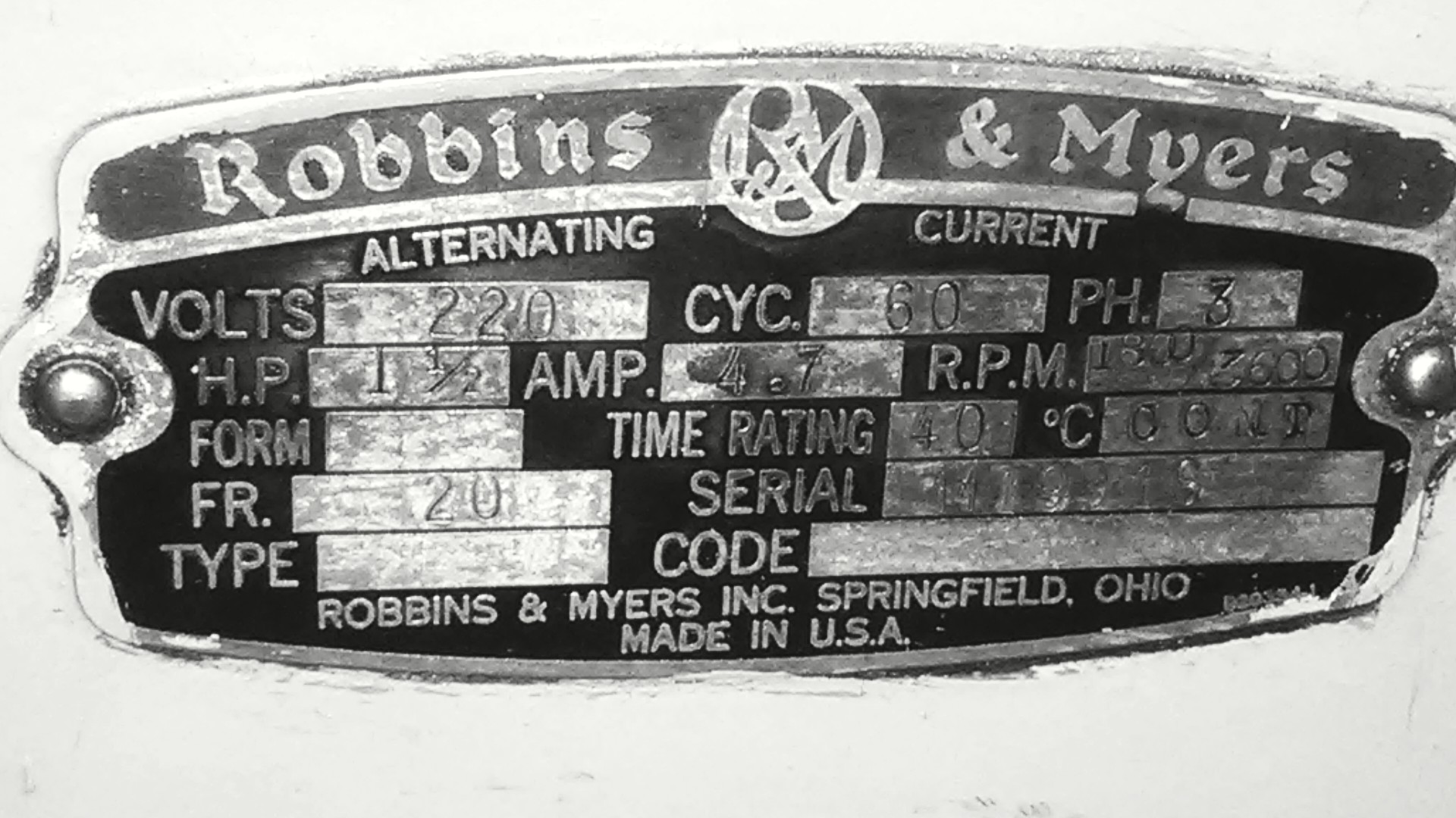
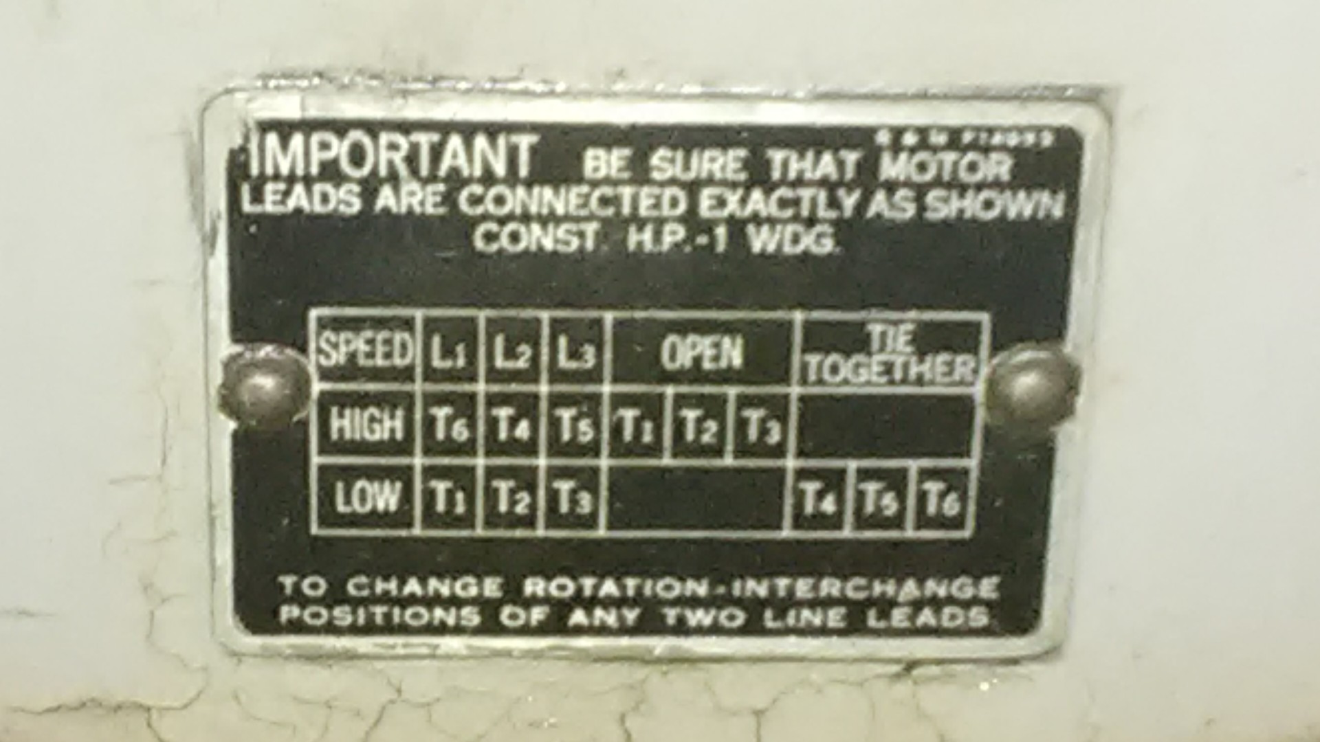
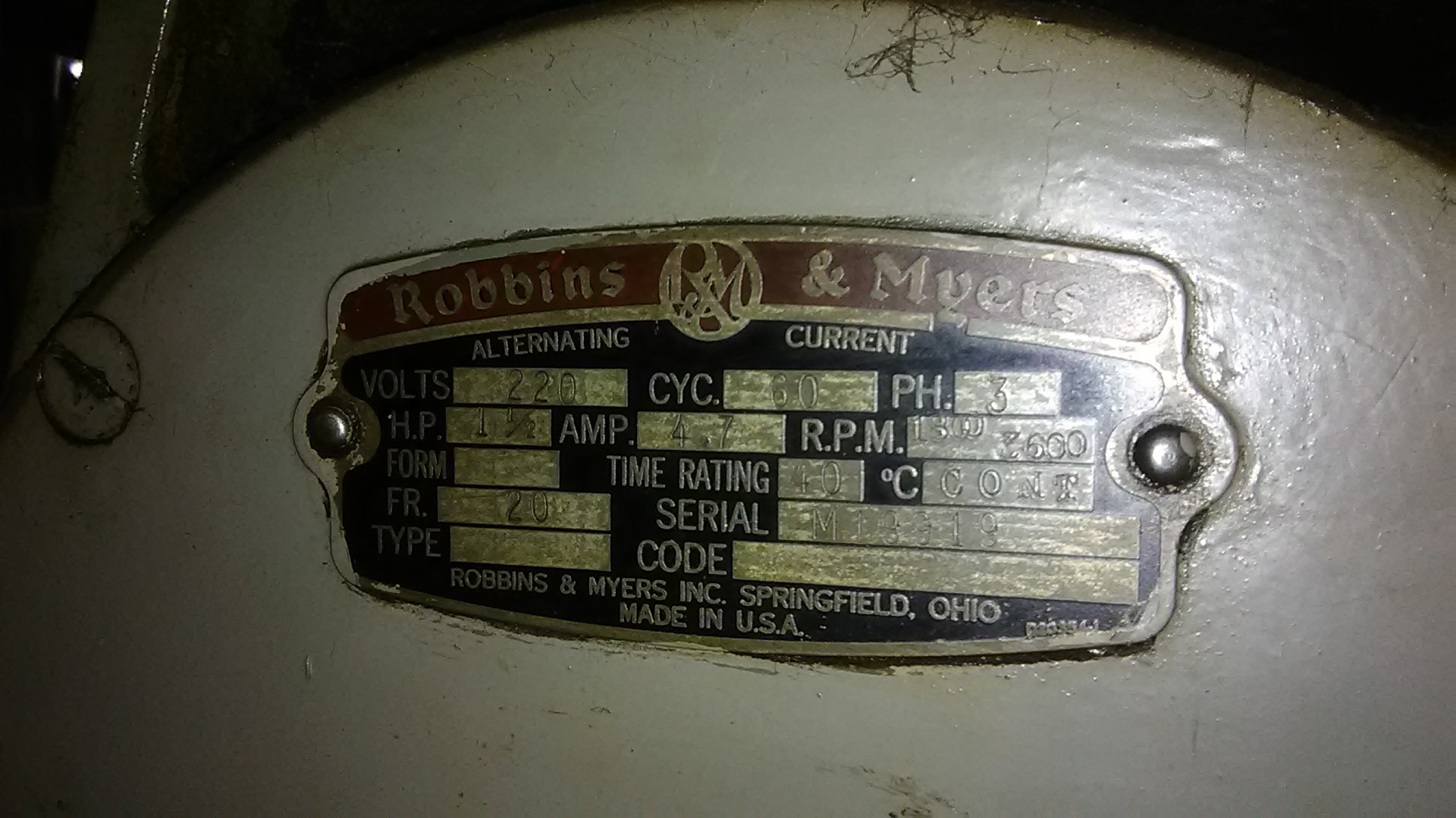
In my defense, the tag was very hard to read until cleaning it better.
Attachment 29100
RPM 1800/3600 60Hz 3PH 220V 4.7A
Attachment 29101
Attachment 29102
Side note, who is emulating who...?
Attachment 29103
I thought it strange that you had a 50 Hz motor in the US.Quote:
Originally Posted by Toolmaker51
Not unusual to find scattered 50Hz machines, rare though to find unmounted 50Hz motors.
I have two machines at 50Hz that will be remedied with VFD's. One is the 50 NM taper Herbert-DeVleig 4B, other a 40 NM Rambaudi.
Most well built 50 Hz motors will tolerate 60 Hz, of course they will run 20% faster and lose some torque if run on the rated voltage.Quote:
Originally Posted by Toolmaker51
I have the opposite, I brought back some machines tools from my time in the US and so I have to run 60 Hz motors at 50 Hz. No problem with 3 ph motors because I run those on VFDs to get full speed, but my lathe has a 2 hp 1 ph motor and so it runs slower than it could. I am currently chasing a 5 hp 3 ph motor to put in its place. I do not need 5 hp but using an oversize motor with a VFD gives good torque at lower speeds than a smaller motor.
As I said before that is a 2/4 pole motor. Today on our favourite auction site I picked up a 5 hp 4/8 pole motor. That means 1500 and 750 rpm. Heavy and big, multipole motors need more iron and copper inside.Quote:
Originally Posted by Toolmaker51
I shall fit it to my lathe which will enable me to ditch the two stage pulley system and noisy back gears and replace them with a pole number switch and VFD. I am hopeful that this will produce a smoother and quieter machine capable of the lowest speed that I am likely to need and a faster machine at the other end.
A close to 1:1 pulley and poly-V belt system should be all I need.
Congrats you just ruined the drill bit look how nice and blue it turned. A split point is fine i done this for over 50 years. You never sharpen a drill bit on the side of the grinding wheel