 LinkBack URL
 About LinkBacks
Yes - cam grinding could use the same type of spindle synced motion.. Andy has also shown that crank grinding could theoretically be done with linuxcnc. (it is just math)
sam
Originally Posted by olderdan


https://www.youtube.com/watch?v=z6dK41_usfQ
sam
Originally Posted by olderdan
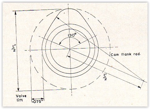
Hi Tony, I was expecting some input from you on this. I should have said generate cams and not turn as tool geometry would be not suitable, I was "Pin It")
Yes - cam grinding could use the same type of spindle synced motion.. Andy has also shown that crank grinding could theoretically be done with linuxcnc. (it is just math
sam
Home-PC (Oct 16, 2020)
There are currently 1 users browsing this thread. (0 members and 1 guests)
 Posting Permissions


 Reply With Quote
Bookmarks