
 LinkBack URL
 About LinkBacks


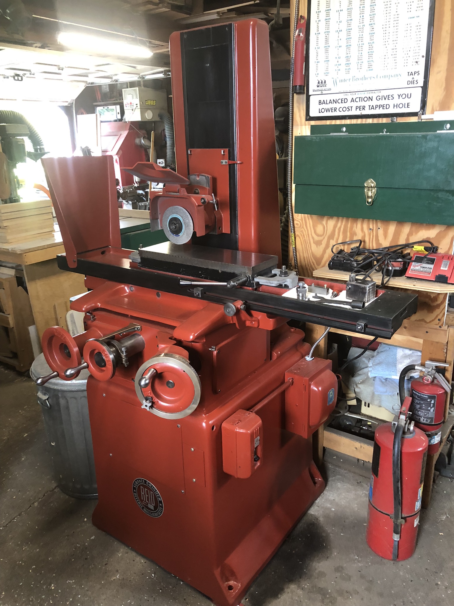
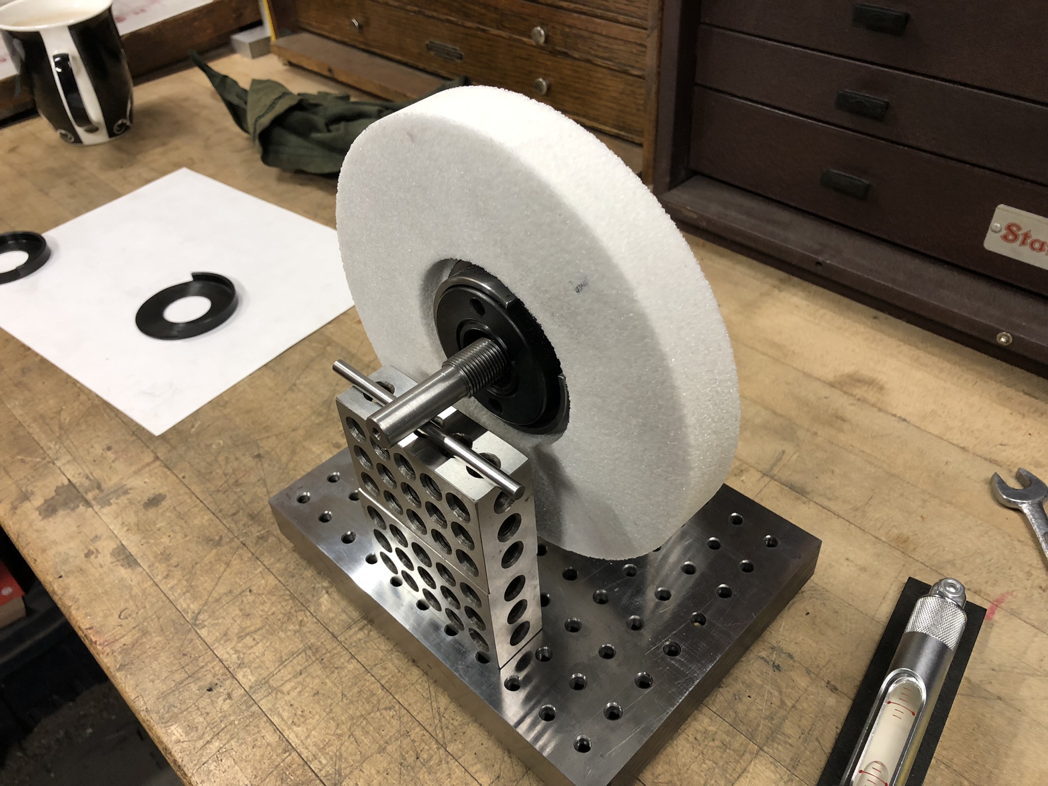
I recently restored a early fifties vintage Ried grinder and am pleased at its performance. I purchased two wheel adapters and wheels. The well used wheels that came with it were fine but the new 7 inch diameter wheels caused some vibration. Not wanting to spend $300+ on balance adapters I found making these counterbalances worked very well.
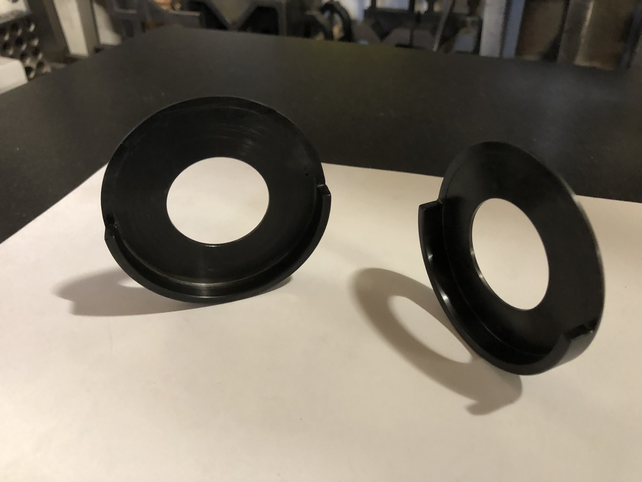
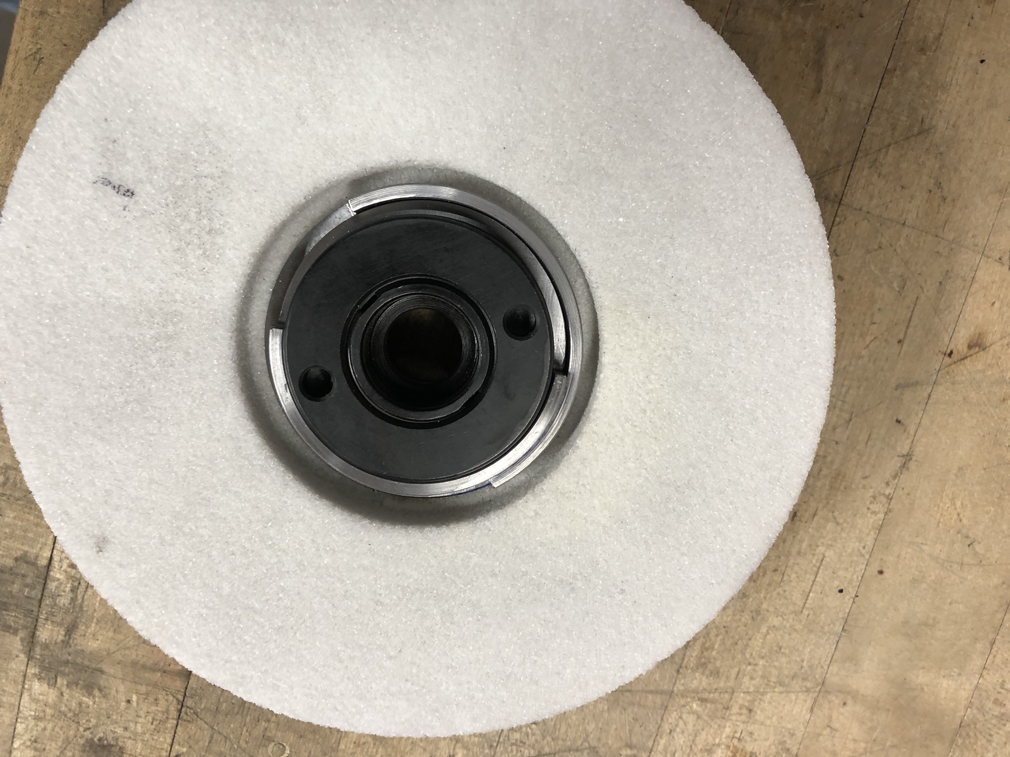
Making two cups, one nesting in the other with one half of the flange removed on each.
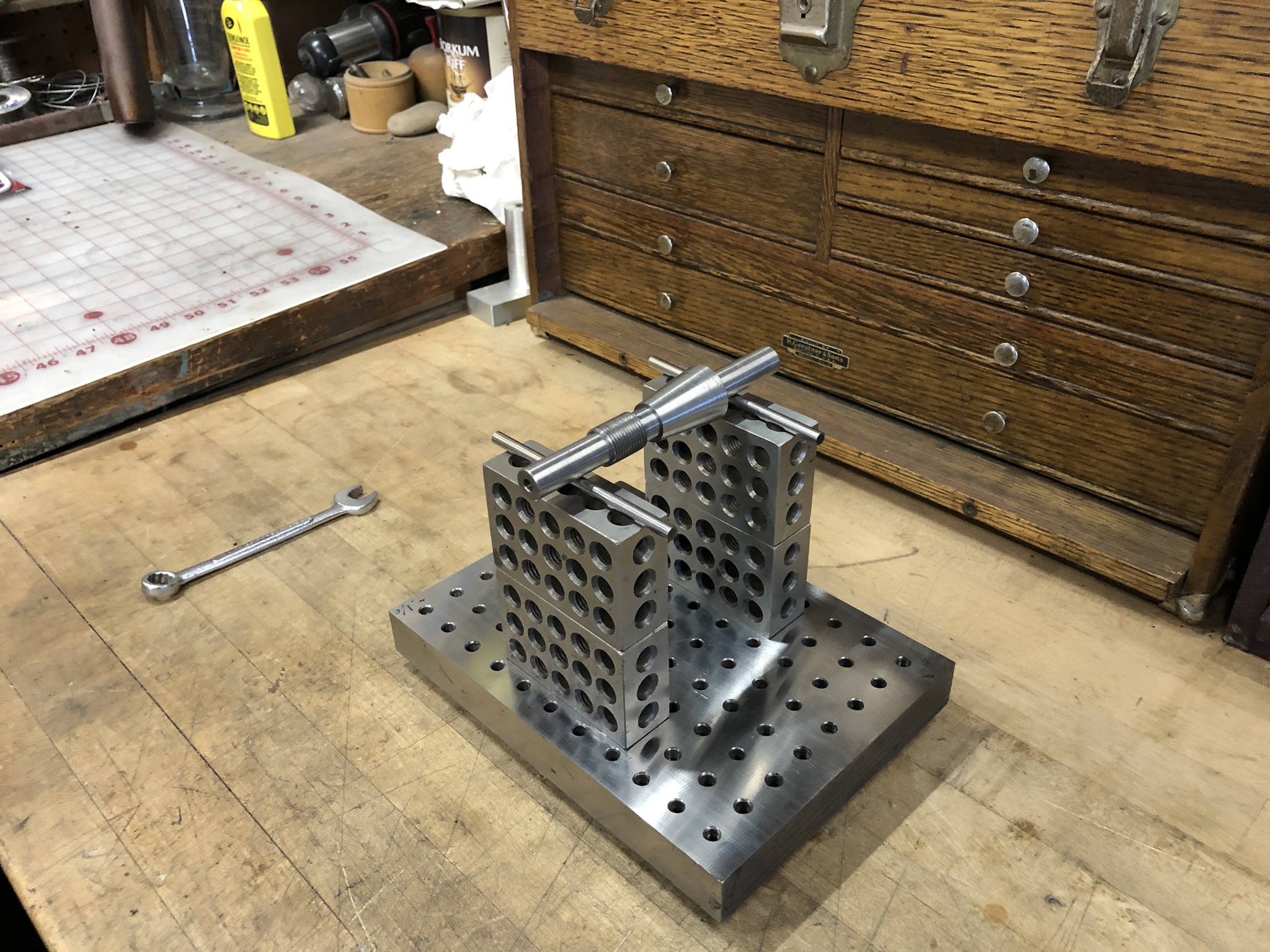
On the balance fixture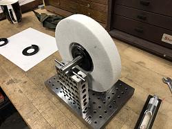


 Reply With Quote

Bookmarks