Free 186 More Best Homemade Tools eBook:  
New: 300+ fresh build posts/day from 275 forums → BuildThreads.com

User Tag List

Results 1 to 3 of 3

Thread: Tail Stock Spider

Threaded View

  1. #1
    Supporting Member hemmjo's Avatar
    Join Date
    Feb 2017
    Posts
    3,301
    Thanks
    410
    Thanked 2,131 Times in 1,230 Posts

    hemmjo's Tools

    Tail Stock Spider

    One of my current projects involves working with 4”
    schedule 40 steel pipe. Specifically truing up the ends
    after band sawing to length, chamfering the ends for welding,
    and cleaning up the outside from welds in its previous life.

    Like many others, in the past a I have used a wooden cone
    shaped plug. The wood plug is typically only good for one
    use. It is not adjustable for good centering. It gets in the way
    of machining the ends. It is time to make a more permanent tool.

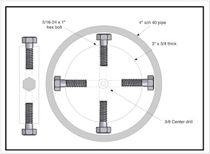
    The spider idea evolved while centering a pipe with the chuck
    jaws on the inside. Putting the initial thoughts on paper
    I get something like this

    01Click image for larger version. 

Name:	01 tailstock spider.jpg 
Views:	155 
Size:	53.5 KB 
ID:	49086

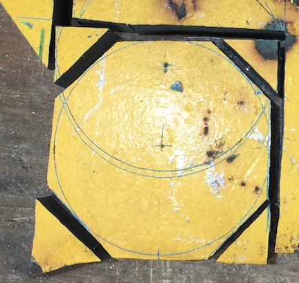
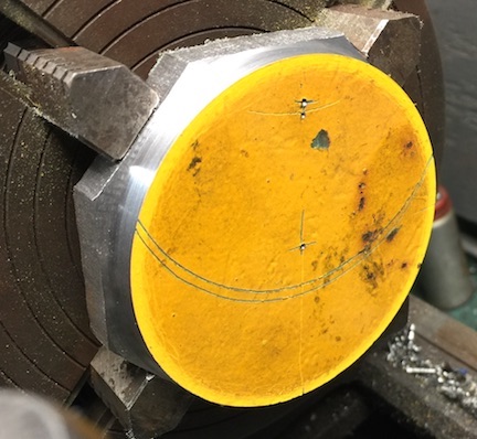
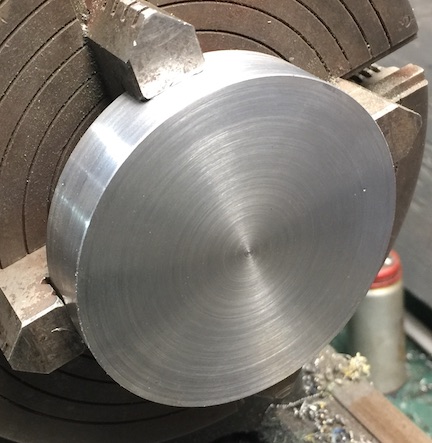
    To get started, Layout out and rough cut a thick disk
    Click image for larger version. 

Name:	02 layout and cut.jpg 
Views:	134 
Size:	75.3 KB 
ID:	49087


    Turn to size
    Click image for larger version. 

Name:	03 turn.jpg 
Views:	119 
Size:	59.9 KB 
ID:	49088


    Finish turn
    Click image for larger version. 

Name:	04 finish turn.jpg 
Views:	99 
Size:	59.0 KB 
ID:	49089


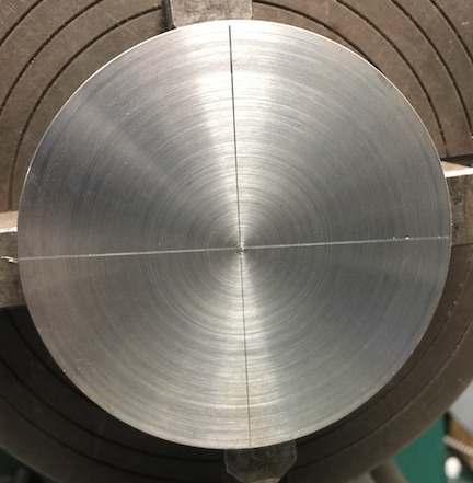
    Scribe for holes using the cross slide and cutting tool.
    Click image for larger version. 

Name:	05 layout.jpg 
Views:	125 
Size:	50.6 KB 
ID:	49090


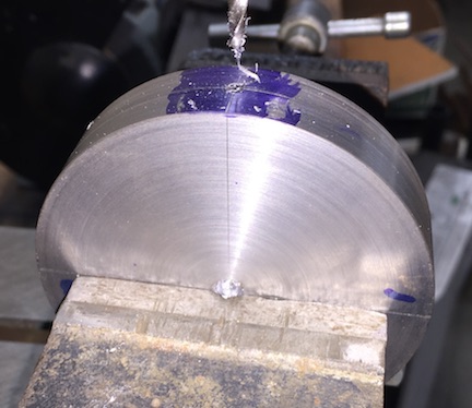
    Transfer scribed lines to the edge, Drill and Tap
    Click image for larger version. 

Name:	06drill and tap.jpg 
Views:	124 
Size:	47.7 KB 
ID:	49091


    The original design needed modification. There was not
    enough room between the body and the inside of the pipe
    to work the wrench when centering the part. In retrospect
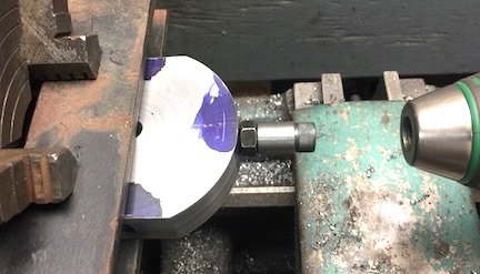
    the body could have just been square. The bolt and sleeve
    were held in the tailstock chuck to hold the part in alignment
    while the chuck is tightened. Steel bars provide more
    support for the part.
    Click image for larger version. 

Name:	07 cut flats.jpg 
Views:	104 
Size:	39.0 KB 
ID:	49092


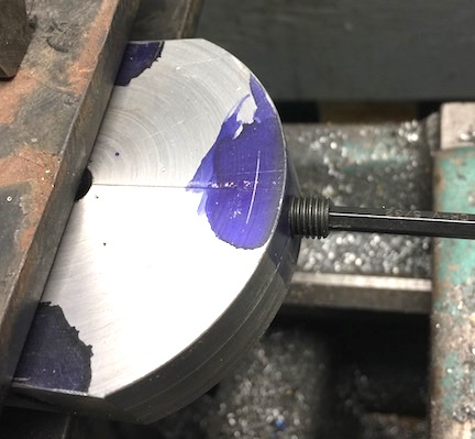
    Since the part was already threaded, insert a set screw.
    Remove after machining to clean up any damaged threads.
    Click image for larger version. 

Name:	08 inset set screw.jpg 
Views:	141 
Size:	44.2 KB 
ID:	49093


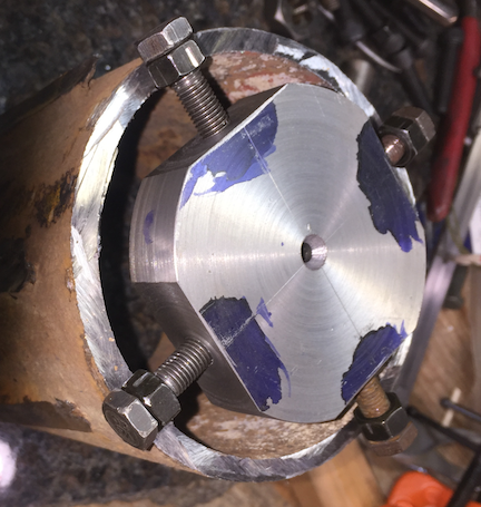
    Note nuts added and jammed against the head of
    the bolts. This provides a better surface for the wrench.
    Click image for larger version. 

Name:	09 ready for trial.png 
Views:	149 
Size:	376.5 KB 
ID:	49094


    A length of PVC pipe was pressed between the spider
    and the chuck which held the spider in position while
    adjusting. NOT an ideal solution.
    Click image for larger version. 

Name:	10 PVC positioner.jpg 
Views:	141 
Size:	45.1 KB 
ID:	49095


    Ready to face end
    Click image for larger version. 

Name:	11 in position.jpg 
Views:	206 
Size:	54.7 KB 
ID:	49096


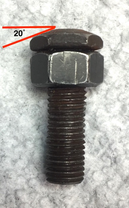
    After the first use, the bolt heads needed to tapered.
    The flat head and hex shape made centering awkward.
    The jam nuts become even more important with
    the head trimmed.
    Click image for larger version. 

Name:	12 Bolt Head.jpg 
Views:	121 
Size:	99.4 KB 
ID:	49097


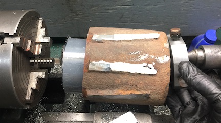
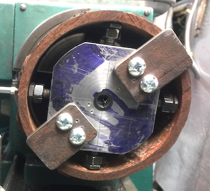
    Removable tabs were added to replace the PVC.
    Click image for larger version. 

Name:	13  locating tabs.jpg 
Views:	125 
Size:	62.0 KB 
ID:	49098


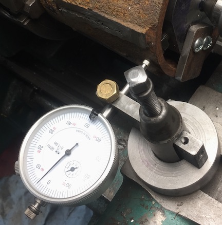
    Dial in the center. Although the surface of the pipe is
    rusty, pitted and the pipe is not perfectly round you can
    still get it pretty close.
    Click image for larger version. 

Name:	14 Dial in center.jpg 
Views:	113 
Size:	58.6 KB 
ID:	49099


    Remove tabs after spider is centered securely in the pipe.
    Click image for larger version. 

Name:	15 tabs removed.jpg 
Views:	121 
Size:	70.8 KB 
ID:	49100


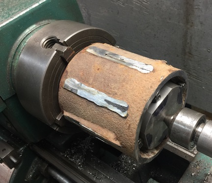
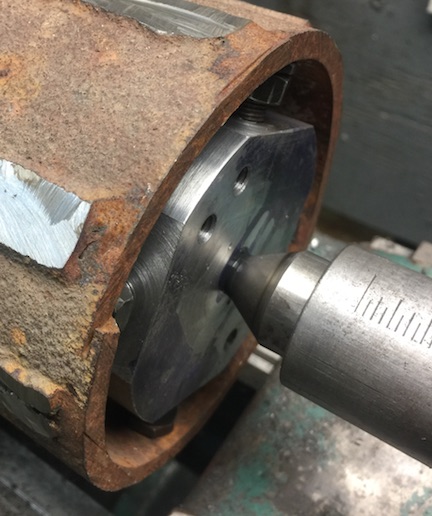
    Face the end. Replace the tabs after facing and slide
    the spider in to be sure there is pressure holding things
    together in case the spider works loose while turning the outside.
    Click image for larger version. 

Name:	16 end  faced.jpg 
Views:	212 
Size:	56.1 KB 
ID:	49101


    The parts
    Click image for larger version. 

Name:	17 parts.jpg 
Views:	135 
Size:	68.8 KB 
ID:	49102


    Click image for larger version. 

Name:	18 Final design.jpg 
Views:	140 
Size:	56.8 KB 
ID:	49103


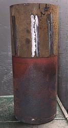
    The goal. Eventually this pipe will be an extension, welded
    to the crucible for my electric furnace. I have to stop at this
    point until I get my furnace back in service. The welds are
    just too hard to effectively machine. Hoping I will be able
    to anneal the whole pipe then finish machining the welds and
    bevel the ends for welding


    Will keep you posted as things progress
    Click image for larger version. 

Name:	19  The Goal.jpg 
Views:	141 
Size:	114.9 KB 
ID:	49104

  2. The Following 8 Users Say Thank You to hemmjo For This Useful Post:

    albertq (Apr 27, 2025), asterix (May 26, 2026), ductape (Apr 25, 2025), emu roo (May 26, 2026), mr mikey (Apr 26, 2025), nova_robotics (Apr 27, 2025), philippacificnw (May 2, 2025), rebuilder1954 (Apr 26, 2025)

Thread Information

Users Browsing this Thread

There are currently 1 users browsing this thread. (0 members and 1 guests)

Bookmarks

Posting Permissions

  • You may not post new threads
  • You may not post replies
  • You may not post attachments
  • You may not edit your posts
  •