
 LinkBack URL
 About LinkBacks


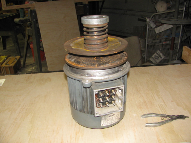
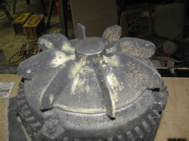
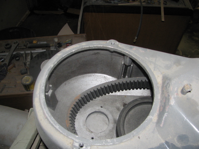
My name is Robert Brown AKA, machiningfool. I hope I am in the right place. A few minutes ago I went to the garage and collected some ideas on how to adapt the treadmill motor to the mill and to my surprise this project will be simple and straight forward. I like to use the KISS principle, keep it simple stupid, stupid being me. After removing the cooling shroud and removing the plastic fan, oh boy there was a 3/4 inch shaft just waiting for a pulley. I am approaching this project with an attitude, that I don't want to get too invasive, so I am going to keep the present 3 phase motor in place along with the variable speed belt system and power the whole mechanism with the treadmill motor. What this does is that I will have complete control of the high and low transmission of the mill and have two ways of controlling speed. One with the built in variable speed belt system and with the variable speed control of the treadmill motor. One advantage of using a treadmill motor is that there is no wiring involved, only placing the controlling electronics where you want them. The only wiring that will be required with this install is a reversing switch. I don't know if this type of adaptation has ever been done, I haven't checked the CNC forum, but I think that this will be a very cheap alternative to the, mill motor go bad situation. Total cost will be, treadmill 55 dollars, two pulleys, one belt. The reversing switch is already on the mill, so will need some short wires. I will attempt to upload some pictures as I watched the video on how to do it. I always like either, way to goes, or raw criticism, they are both appreciated. Robert Brown. Here are some pics., I hope.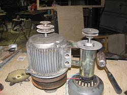


 Reply With Quote

Bookmarks