
 LinkBack URL
 About LinkBacks


Ok some background so you can understand me.
Im a farmers son who hates spending money unless its absolutely necessary, you can never fix problems by throwing money at it.
and every thing i make usually comes from my stash of collected items or items gifted by friends (ie stepper drives from paint mixing machines).
Space is a premium but i have still not acquired the knowledge that my workshop isn’t a tardis.
So progress on the machine this week.
I continued working on the coolant system, I had to buya coolant pump. The old pump from the machine had flow issues, it was like the flow rate from a urinating toddler - yes it dribbled more down itself than succeeded in aiming at the work piece.
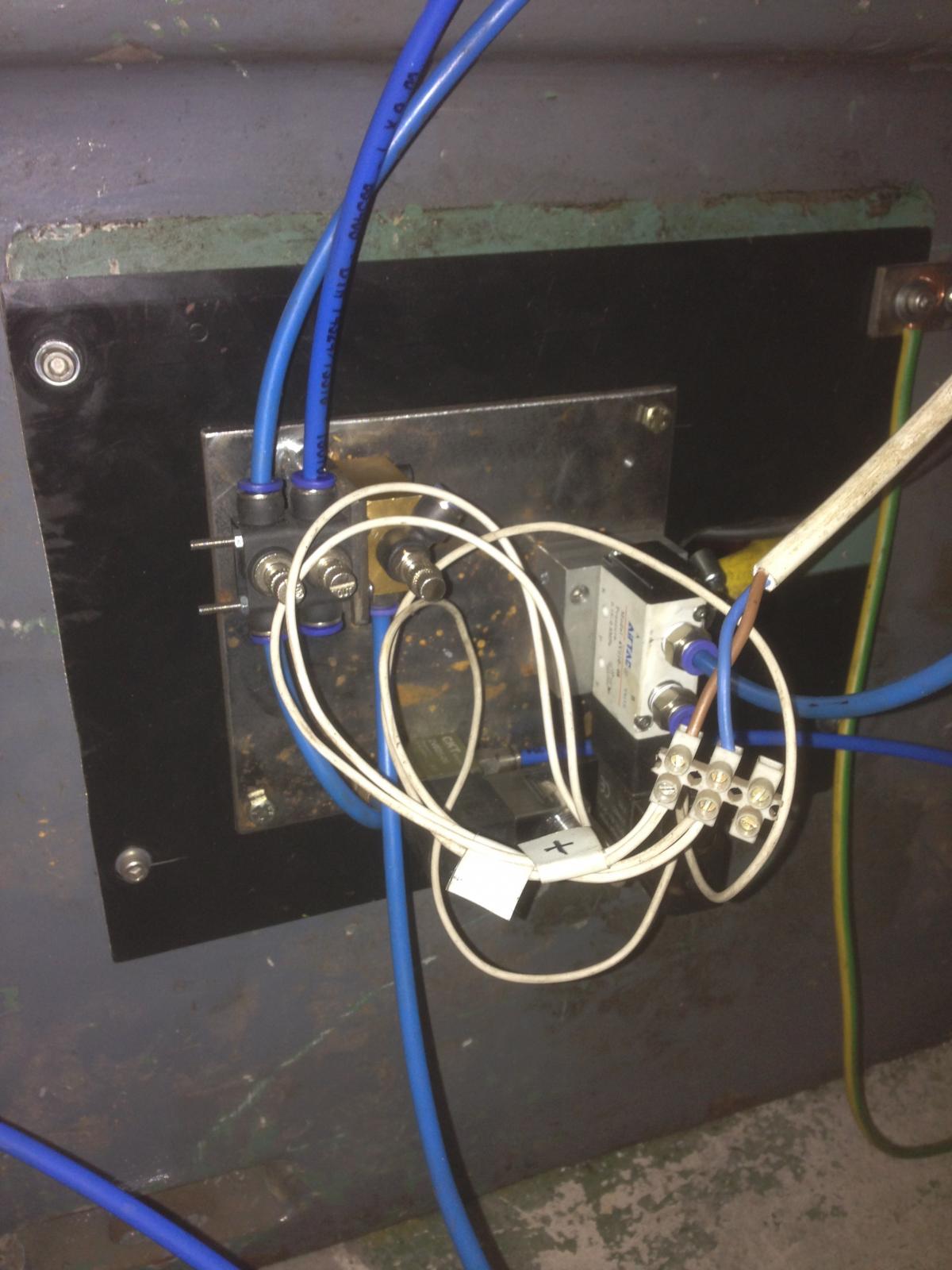
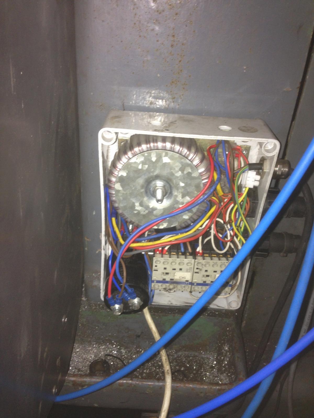
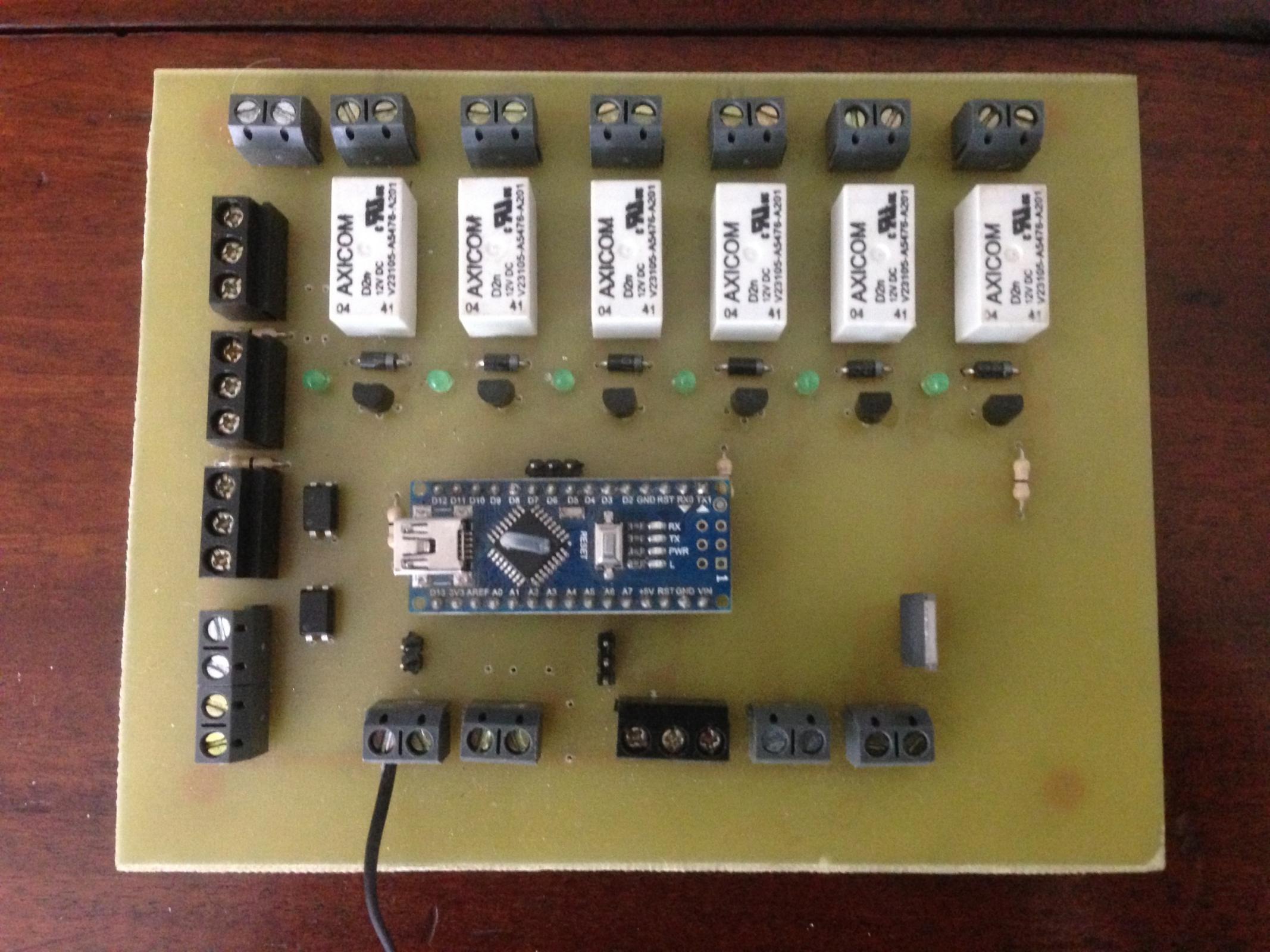
A control panel was built which provided both flood and mist coolant options (Gcode M7 & M8), the plan was that with either option the flood coolant pump would run. option 1 would simply divert the flow directly to the work piece and option 2 supply coolant to the mist via a venturi so that i wouldn’t need a separate reservoir.
It failed
The (pneumatic) solenoid valve i was using to divert coolant flow just leaked like a sieve and its output was negligible. Before an academic jumps in here, you can use pneumatic and hydraulic parts in either system its the same only the media is different, air, water, oil. Pressure is a concern pneumatics wont work well over 120 psi and hydraulics well pressures in excess of 3000 psi is normal (Im trained to work with high pressure systems exceeding 10k psi).
My conclusion other than a leaking seal is that the 1/16 hole in the valve is more of a hindrance than anything else especially added to the fact i was using 1/8 hose.
The fitting size on the pump was a bit of a giveaway at 1/2".
im now in the process of "rip up and retry" so back to 2 separate systems with the mist having a reservoir, i could automate the top up of the mist circuits reservoir but it may not be worth it.
The machine panels have started to go back on and the probing circuits have been tested (both tool height setter and active probe)
The build has some limitations which i hoped would iron out, Pathpilot by default has a feed rate of 2 meters min, my setup will only allow 500mm/min which is fine for what i intend to use my mill for (im usually between 75 and 250 mm/min for most operations) But oh it would be so nice to get 2mtr/min. i suspect hat the bed ways on the mill being old metal guide ways is too much friction for the stepper motors to deal with. we are not going to put linear rails on it. Butchering such a fine old piece of British industrial heritage ( Elliott's in London) is just a step too far.
I have tinkered so much inside PP's configuration now I probably know as much about tormach's as they do.
A young gent as acquired my assistance in converting his mill, he had approached me as he also was wishing to covert his machine and had also acquired pathpilot. He has a Denford Desktop mill which i have started to call his Etch-a-sketch. His configuration also had to be dialled down, which is just as well as this thing would have thrown itself off the bench at 2 mtr/min.
At some point in the next week in going to grow a pair and try my first cuts, before then i need to do some serious clip recording and images taken to add to this post for you guys/gals.
Always been someone with more than one project on the go, this time is no different.
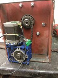
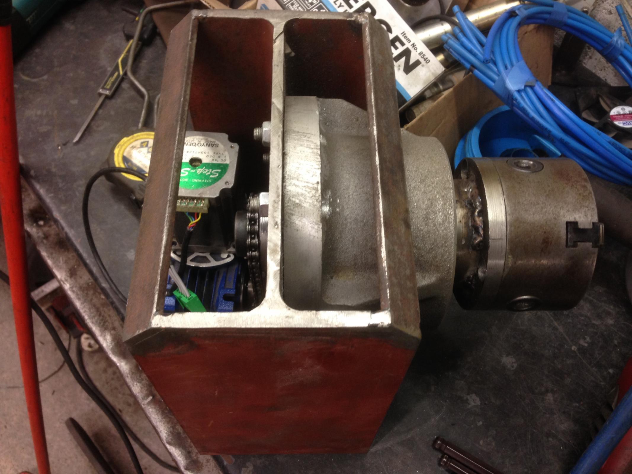
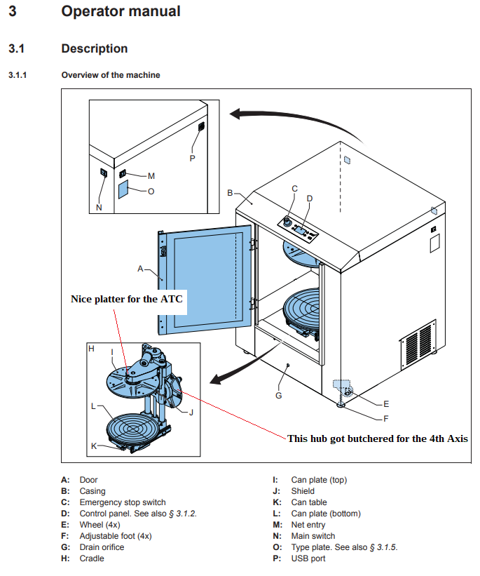
I have been quietly chipping away on three side projects but very much related, A Power Drawbar, an Auto Tool changer and a 4th axis.
so in the intro to this post i mentioned i liked building things from available scrap and not spending dosh. well.
The 4th axis is making its way slowly but surely out of the scraps box and into fruition


 Reply With Quote
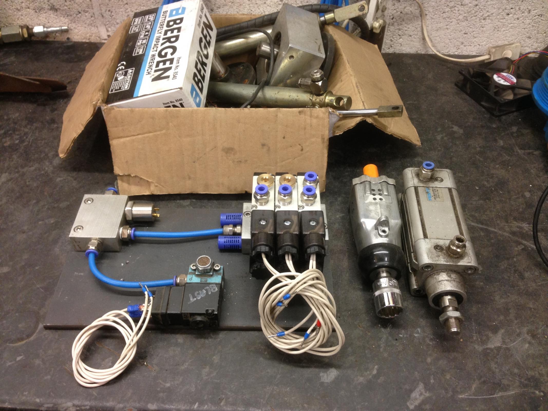


Bookmarks